Snmp Manager Snmp Settings — D-link DES-3028 User Manual
Содержание:
SNMP Manager
SNMP Settings
Simple Network Management Protocol (SNMP) is an OSI Layer 7 (Application Layer) designed specifically for managing and
monitoring network devices. SNMP enables network management stations to read and modify the settings of gateways, routers,
switches, and other network devices. Use SNMP to configure system features for proper operation, monitor performance and
detect potential problems in the Switch, switch group or network.
Managed devices that support SNMP include software (referred to as an agent), which runs locally on the device. A defined set of
variables (managed objects) is maintained by the SNMP agent and used to manage the device. These objects are defined in a
Management Information Base (MIB), which provides a standard presentation of the information controlled by the on-board
SNMP agent. SNMP defines both the format of the MIB specifications and the protocol used to access this information over the
network.
The DES-3028/28P/28G/52/52P supports the SNMP versions 1, 2c, and 3. The default SNMP setting is enabled and cannot be
disabled. The three versions of SNMP vary in the level of security provided between the management station and the network
device.
In SNMP v.1 and v.2, user authentication is accomplished using ‘community strings’, which function like passwords. The remote
user SNMP application and the Switch SNMP must use the same community string. SNMP packets from any station that has not
been authenticated are ignored (dropped).
The default community strings for the Switch used for SNMP v.1 and v.2 management access are:
public — Allows authorized management stations to retrieve MIB objects.
private — Allows authorized management stations to retrieve and modify MIB objects.
SNMPv3 uses a more sophisticated authentication process that is separated into two parts. The first part is to maintain a list of
users and their attributes that are allowed to act as SNMP managers. The second part describes what each user on that list can do
as an SNMP manager.
The Switch allows groups of users to be listed and configured with a shared set of privileges. The SNMP version may also be set
for a listed group of SNMP managers. Thus, you may create a group of SNMP managers that are allowed to view read-only
information or receive traps using SNMPv1 while assigning a higher level of security to another group, granting read/write privi-
leges using SNMPv3.
Using SNMPv3 individual users or groups of SNMP managers can be allowed to perform or be restricted from performing
specific SNMP management functions. The functions allowed or restricted are defined using the Object Identifier (OID)
associated with a specific MIB. An additional layer of security is available for SNMPv3 in that SNMP messages may be
encrypted. To read more about how to configure SNMPv3 settings for the Switch read the next section.
Traps
Traps are messages that alert network personnel of events that occur on the Switch. The events can be as serious as a reboot
(someone accidentally turned OFF the Switch), or less serious like a port status change. The Switch generates traps and sends
them to the trap recipient (or network manager). Typical traps include trap messages for Authentication Failure, Topology Change
and Broadcast\Multicast Storm.
MIBs
The Switch in the Management Information Base (MIB) stores management and counter information. The Switch uses the
standard MIB-II Management Information Base module. Consequently, values for MIB objects can be retrieved from any SNMP-
based network management software. In addition to the standard MIB-II, the Switch also supports its own proprietary enterprise
MIB as an extended Management Information Base. Specifying the MIB Object Identifier may also retrieve the proprietary MIB.
MIB values can be either read-only or read-write.
The DES-3028/28P/28G/52/52P incorporates a flexible SNMP management for the switching environment. SNMP management
can be customized to suit the needs of the networks and the preferences of the network administrator. Use the SNMP V3 menus to
select the SNMP version used for specific tasks.
The DES-3028/28P/28G/52/52P supports the Simple Network Management Protocol (SNMP) versions 1, 2c, and 3. The
administrator can specify the SNMP version used to monitor and control the Switch. The three versions of SNMP vary in the level
of security provided between the management station and the network device.
57
Пример настройки коммутатора D-Link DES-3550
04.04.2013

|
1 |
reset create vlan vlanid2 config vlan vlanid1delete1-50 config vlan vlanid2add tagged49-50name manag config ipif System ipaddress192.168.2.14124 config ipif System vlan manag enable password encryption create account admin admin enable loopdetect config loopdetect recover_timer60 config loopdetect interval10 config loopdetect ports1-50state enabled config loopdetect ports49state disabled enable snmp traps enable snmp authenticate traps config snmp system_name SW_2-141 config snmp system_contact admin@domain.ru enable rmon disable asymmetric_vlan config vlan defaultadvertisement enable config vlan manag advertisement disable config ipif System vlan manag ipaddress192.168.2.14124state enabled disable autoconfig enable web config command_prompt SW_2-141 config filter dhcp_server ports1-48 enable sntp config time_zone operator+hour4min config sntp primary192.168.2.129secondary0.0.0.0poll-interval720 config dst disable create access_profile ip udp src_port_mask0xFFFFprofile_id1 config access_profile profile_id1add access_id auto_assign ip udp src_port67port49-50permit config access_profile profile_id1add access_id auto_assign ip udp src_port67port1-48deny create access_profile ip tcp dst_port_mask0xffffprofile_id2 config access_profile profile_id2add access_id auto_assign ip tcp dst_port42port1-48deny config access_profile profile_id2add access_id auto_assign ip tcp dst_port135port1-48deny config access_profile profile_id2add access_id auto_assign ip tcp dst_port139port1-48deny config access_profile profile_id2add access_id auto_assign ip tcp dst_port445port1-48deny config access_profile profile_id2add access_id auto_assign ip tcp dst_port593port1-48deny config access_profile profile_id2add access_id auto_assign ip tcp dst_port2869port1-48deny config access_profile profile_id2add access_id auto_assign ip tcp dst_port5000port1-48deny create access_profile ip udp dst_port_mask0xffffprofile_id3 config access_profile profile_id3add access_id auto_assign ip udp dst_port42port1-49deny config access_profile profile_id3add access_id auto_assign ip udp dst_port137port1-49deny |
Коммутаторы
Preface
The DES-3028/DES-3028P/DES-3052/DES-3052P User Manual is divided into sections that describe the system installation and
operating instructions with examples.
Section 1, Introduction — Describes the Switch and its features.
Section 2, Installation — Helps you get started with the basic installation of the Switch and also describes the front panel, rear
panel, side panels, and LED indicators of the Switch.
Section 3, Connecting the Switch — Tells how you can connect the Switch to your Ethernet/Fast Ethernet network.
Section 4, Introduction to Switch Management — Introduces basic Switch management features, including password protection,
SNMP settings, IP address assignment and connecting devices to the Switch.
Section 5, Introduction to Web-based Switch Management — Talks about connecting to and using the Web-based switch
management feature on the Switch.
Section 6, Administration — A detailed discussion about configuring the basic functions of the Switch, including Device
Information, IP Address, Port Configuration, DHCP/BOOTP Relay, User Accounts, Port Mirroring, System Log Settings, Log
Settings, SNTP Settings, MAC Notification Settings, TFTP Services, Multiple Image Services, Ping Test, Safeguard Engine,
SNMP Manager, PoE System, Single IP Settings, Forwarding & Filtering, and SMTP Service.
Section 7, Layer 2 Features — A discussion of Layer 2 features of the Switch, including VLAN, Trunking, IGMP Snooping, and
Spanning Tree.
Section 8, CoS — Features information on CoS, including Port Bandwidth, 802.1P Default Priority, 802.1P User Priority, CoS
Scheduling Mechanism, CoS Output Scheduling, Priority Settings, TOS Priority Settings, DSCP Priority Settings, Port Mapping
Priority Settings, and MAC Priority.
Section 9, ACL — Discussion on the ACL function of the Switch, including Time Range, Access Profile Table and CPU Interface
Filtering.
Section 10, Security — A discussion on the Security functions on the Switch, including Traffic Control, Port Security, Port Lock
Entries, SSL, SSH, 802.1X, Trusted Host, Access Authentication Control, and Traffic Segmentation.
Section 11, Monitoring — Features information on Monitoring including CPU Utilization, Port Utilization, Packets, Packet Errors,
Packet Size, MAC Address, Switch Log, IGMP Snooping Group, Browse Router Port, Static ARP Settings, Session Table, and
Port Access Control.
Appendix A, Technical Specifications — Technical specifications for the DES-3028/DES-3028P/DES-3052 and the DES-3052P.
Appendix B, System Log Entries — Information on the System Log Entries
Appendix C, Cable Lengths — Information on cable types and maximum distances.
Appendix D, Glossary — Lists definitions for terms and acronyms used in this document.
vii
Транскрипт
1 Настройка Асимметричных VLAN для разделения общих ресурсов используя коммутаторы D-Link 2 уровня
2 Совместно используемые информационные ресурсы бщие ресурсы/серверы (почтовые серверы, файл-серверы, FTP/HTTP службы) могут ыть доступны всем пользователям в группах VLAN1, VLAN2, VLAN3, но доступ между обой этим группам не разрешен (для обеспечения производительности или для беспечения политики безопасности) ешение на коммутаторах 2 уровня: Асимметричные VLAN или Traffic Segmentation ешение на коммутаторах 3 уровня: Коммутатор 3 уровня + ACL (списки доступа) для граничения доступа между группами
3 Асимметричные VLAN в сравнении с Traffic Segmentation Асимметричные VLAN: — Необходимы хорошие знания стандарта 802.1q — Участники VLAN могут быть на разных коммутаторах, и общие ресурсы (напр., сервер) могут находится где угодно. — Необходима специальное расширение для 802.1q (возможность использования одного и того же порта Untagged в нескольких VLAN ) — Может не поддерживаться IGMP snooping — Максимальное количество VLAN ограничено 4096 Traffic Segmentation: — Простота настройки, нет необходимости в знании 802.1q — Участники одной группы не могут быть подключены к разным коммутаторам — IGMP snooping будет работать по прежнему. — Traffic Segmentation может быть представлен в виде иерархического дерева. Нет ограничений на создание групп. — Общие ресурсы/сервера должны быть на вершине коммутатора (когда используется иерархическая структура)
4 Пример1: Асимметричные VLAN V1 V1 Интернет-шлюз V2 V3 V1: порты 1-8, untagged Общедоступные сервера или Интернет-шлюз. V2: порты 9-16, untagged VLAN2 пользователи (компьютеры и/или серверы) V3: порты 17-24, untagged VLAN3 пользователи ( компьютеры или коммутаторы) Необходимые условия V2 и V3 могут получать доступ к V1 (с использованием IPX, других протоколов IP, AppleTalk, NetBEUI и т.д.) V2 и V3 могут получать доступ с Интернет-шлюзу для доступа в интернет используя ту же сеть IP. Группы V2 и V3 между собой общаться не должны.
5 Пример1: Асимметричные VLAN PVID and VLAN settings: ports =============================== pvid VLANS default E..E E..E E..E (V1) U..U U..U U..U V2 E..E E..E -..- U..U U..U -..- V3 E..E -..- E..E U..U -..- U..U enable asymmetric_vlan create vlan v2 tag 2 create vlan v3 tag 3 config vlan v2 add untagged 1-16 config vlan v3 add untagged 1-8,17-24 config gvrp 1-8 pvid 1 config gvrp 9-16 pvid 2 config gvrp pvid 3 save Тест: Компьютеры из группы V2 получают доступ к группе V1 и интернет-шлюзу. Проверяется командой ping Компьютеры из группы V3 получают доступ к группе V1 и интернет-шлюзу. Компьютеры из группы V2 не могут видеть компьютеры из группы V3 и наоборот.
6 Пример 2: Асимметричные VLAN Различные VLAN имеют различный уровень доступа V1, Сервера, SRV1 VLAN2 V2, Интернет-шлюз SRV1: ports 1,2 Интернет-шлюз: ports 3,4 VLAN3: 5-8 VLAN4: 9-16 VLAN5: Необходимые условия: V3 имеет доступ к V1 SRV1, но не имеет доступа к V2. V4 имеет доступ к V1, и к V2 V5 имеет доступ к V2, но не имеет доступа к V1. V3, V4, V5 не имеют доступа к друг другу. V3 V4 V5
7 Пример 2: Асимметричные VLAN Различные VLAN имеют различный уровень доступа PVID and VLAN settings: VLAN V1 V2 V3 V4 V5 ports ================================================= pvid default E..E E..E E..E E..E — (V1) U..U U..U U..U U..U — V2 E..E E..E — E..E E..E U..U U..U — U..U U..U V3 E..E — E..E U..U — U..U V4 E..E E..E — E..E — U..U U..U — U..U — V5 — E..E E..E — U..U U..U
8 Пример 2: Асимметричные VLAN Различные VLAN имеют различный уровень доступа enable asymmetric_vlan # default vlan is created by default create vlan v2 tag 2 create vlan v3 tag 3 create vlan v4 tag 4 create vlan v5 tag 5 config vlan default delete config vlan v2 add untagged 1-4,9-24 config vlan v3 add untagged 1-2,5-8 config vlan v4 add untagged 1-4, 9-16 config vlan v5 add untagged 3-4, Группа V3 имеет доступ к V1, но не имеет доступа к V2, и другим VLANs (V4, V5) Группа V4 имеет доступ к V1 и V2, но не имеет доступ к V5. Группа V5 имеет доступ к V2, но не имеет доступ к V1. config gvrp 1-2 pvid 1 config gvrp 3-4 pvid 2 config gvrp 5-8 pvid 3 config gvrp 9-16 pvid 4 config gvrp pvid 5 save
9 Ограничение асимметричных VLAN IGMP Snooping не поддерживается при использовании асимметричных VLAN. Решение: Использование коммутатора 3 уровня + ACL(листы доступа) + многоадресная (multicasting) маршрутизация + IGMP snooping При использовании Assymetric VLAN не происходит изучение, а также добавление в таблицы коммутации, MAC-адресов с тегированных портов. Тем самым применение Assymetric VLAN ограничивается одним коммутатором.
Настройка VLAN на D-Link DIR-100300, 615.
D-Link DIR-100 недорогой коммутатор с поддержкой виртуальной сети VLAN. Конечно, отсутствие WiFi на данном устройстве делает его практически непривлекательны с точки зрения многофункциональности.
Но после перепрошивки коммутатора, его можно легко превратить в полноценный коммутатор VLAN. Конечно, его возможно от этого не вырастут, но для стоимости в ценовом сегменте «до 1000 рублей» эти самые возможности весьма приличные. Также не помешает обновить файлы: d3dx9 42.dll скачать и steam api64.dll скачать.
В качестве примера будет рассмотрен вариант настройки одного VLAN для управления коммутатором, а все три остальные будут преобразованы в отдельную сеть. Это часто необходимо для того, чтобы подключиться к Интернету можно было только по одной VLAN.
Итак, заходим в параметры устройства и выбираем меню VLAN Group Settings. Вообще эта модель роутера позволяет создавать до 8 сетей, но для нашего примера достаточно всего двух одна для управления и вторая для подключения к сети. Все поля должны быть заполнены следующим образом:
В первую очередь активируем интерфейс поставив галочку Enable, далее в поле VID вводим номер необходимой нам сети, после чего указываем те порты LAN, с которых будет производиться доступ, и помечаем их как Untag. Отмечаться нужным тегом активные VLAN в нашем случае будут на базе порта WAN отмечаем его, как Tag.
В нашем случае основная сеть у нас Vlan 1, в ее составе находится 4-й порт и наружу она не выходит, то есть на внешнем порту ее просто не будет. Во второй Vlan находятся порты 5,3 и 2, которые тегируются на порту WAN. Кроме того, в Management VLAN Settings нужно установить значение Management VID для нашего случая это «1». Нажиманием на кнопку «Ок».
Теперь займемся настройкой PVID для портов перейдем в меню Port VID Settings. В данном разделе нужно поставить PVID только тем портам, для которых мы указали значение Untag. Разумеется, идентификатор PVID будет полностью соответствовать номеру сети, к которой он подключен.
Значение PVID на WAN порте менять мы не будем, оставляем значение по умолчанию. PVID WAN порта нужно изменить только в том случае, если он отмечен как Unteg. Сохраняем настройки.
Все, нужные опции мы изменили, теперь устройство нужно перезагрузить, и можно наслаждаться его работой.
Настройка D-Link DIR-100 D1 коммутатор VLAN
Описание: Прошивка оборудования vlan switch IP-адрес по умолчанию 192.168.0.1 вход (как зайти в роутер 192.168.1.1), для входа в веб-интерфейс User Name admin, пароль оставляем пустым. Настройка маршрутизатора DIR-100 для подключения услуг IPTV (трафик тегированный) 1, 2 порт и интернет (трафик нетегированный) используем для подключения 3 или 4 порт (авторизацию PPPoE поднимаем после маршрутизатора, например на компьютере). Управляющий vlan на маршрутизаторе 1, поэтому что бы не потерять управление оставляем 1 на портах 3,4 и 5 (wan).
-
Подключение и настройка роутера Wi-Fi.
- Как выбрать Wi-Fi роутер, беспроводной маршрутизатор для дома.
- Роутер Sagemcom fast 2804.
- Как настроить VLAN на коммутаторе D-Link DIR-100(300, 615) (vlan switch).
- Как настроить беспроводную точку доступа D-Link DWL-2100AP.
- Как настроить модем, роутер Интеркросс ICxDSL 5633 E.
- Как настроить маршрутизатор D-Link dir-300, 615 b5 для Ростелеком.
- Как настроить маршрутизатор, Wi-Fi роутер D-Link DIR-300/A/D1 под российских провайдеров.
- Как настроить ADSL роутер-маршрутизатор RT-A1W4L1USBn от QTech под Ростелеком.
- Как настроить и подключить Wi-Fi роутер, подключение к Интернету.
Также читайте…
- Ростелеком, STB IPTV-приставка HD 101 (HD103) от Промсвязи.
- Как посмотреть историю в Интернете, на ноутбуке и ПК,
- Роутер Sagemcom fast 2804.
Асимметричный VLAN
В терминологиях D-Link, а также в настройках VLAN, есть понятие асимметричный VLAN – это такой VLAN, в котором один порт может быть в нескольких VLAN. Состояние портов меняется:
- Tagged порты работают прежним образом
- Появляется возможность назначать как Untagged несколько портов на несколько VLAN. Т.е. один порт сразу работает в нескольких VLAN как Untagged
- У каждого порта появляется еще один параметр PVID — это VLAN ID, которым маркируется трафик с этого порта, если он уходит на Tagged порты и за пределы коммутатора. У каждого порта может быть только один PVID
Таким образом, мы получаем то, что внутри устройства один порт может принадлежать сразу нескольким VLAN, но при этом, уходящий в tagged (TRUNK) порт, трафик будет маркироваться номером, который мы задаем в PVID.
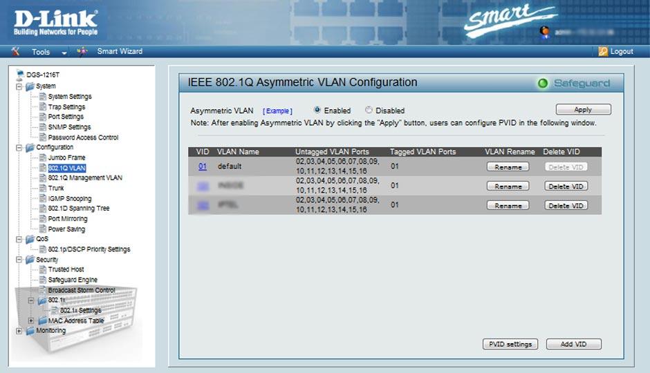
Ограничение: Функция IGMP Snooping не работает при использовании асимметричных VLAN.
ISM VLAN Settings
In a switching environment, multiple VLANs may exist. Every time a multicast query passes through the Switch, the switch must
forward separate different copies of the data to each VLAN on the system, which, in turn, increases data traffic and may clog up
the traffic path. To lighten the traffic load, multicast VLANs may be incorporated. These multicast VLANs will allow the Switch
to forward this multicast traffic as one copy to recipients of the multicast VLAN, instead of multiple copies.
Regardless of other normal VLANs that are incorporated on the Switch, users may add any ports to the multicast VLAN where
they wish multicast traffic to be sent. Users are to set up a source port, where the multicast traffic is entering the switch, and then
set the ports where the incoming multicast traffic is to be sent. The source port cannot be a recipient port and if configured to do
so, will cause error messages to be produced by the switch. Once properly configured, the stream of multicast data will be relayed
to the receiver ports in a much more timely and reliable fashion.
Restrictions and Provisos
The Multicast VLAN feature of this switch does have some restrictions and limitations, such as:
1. Multicast VLANs can be implemented on edge and non-edge switches.
2. Member ports and source ports can be used in multiple ISM VLANs. But member ports and source ports cannot be the
same port in a specific ISM VLAN.
3. The Multicast VLAN is exclusive with normal 802.1q VLANs, which means that VLAN IDs (VIDs) and VLAN Names
of 802.1q VLANs and ISM VLANs cannot be the same. Once a VID or VLAN Name is chosen for any VLAN, it cannot
be used for any other VLAN.
4. The normal display of configured VLANs will not display configured Multicast VLANs.
5. Once an ISM VLAN is enabled, the corresponding IGMP snooping state of this VLAN will also be enabled. Users
cannot disable the IGMP feature for an enabled ISM VLAN.
6. One IP multicast address cannot be added to multiple ISM VLANs, yet multiple Ranges can be added to one ISM VLAN.
The following windows will allow users to create and configure multicast VLANs for the switch. To view these windows, click
L2 Features > IGMP Snooping > ISM VLAN Settings.
The previous window displays the settings for previously created Multicast VLANs. To view the settings for a previously created
multicast VLAN, click the Modify button of the corresponding ISM VLAN you wish to modify. To create a new Multicast VLAN,
click the
add new entry
link in the top left-hand corner of the screen, which will produce the following window to be configured.
Figure 7- 22. IGMP Snooping Multicast VLAN Settings – Add window
Enter a name for the ISM VLAN into the VLAN Name field and choose a VID between 2 and 4094. Entries in these two fields
must not have been previously configured on the switch or an error message will be prompted to the user. Once these two fields
have been filled, click the Apply button, which will automatically adjust the current window to resemble the following window.
Figure 7- 21. IGMP Snooping Multicast VLAN Table window
108