Настройка оборудования Ubiquiti
Содержание:
- Основные понятия и подключение
- Initial Configuration for Transparent Bridge Mode
- Вы получаете
- Преимущества
- Configuring Bridge Mode for Gateways
- Routing and Bridges
- Introduction to Bridge Mode
- Table of Contents
- Initial Steps
- Configuration for Radio Labeled 192.168.1.2
- Configuration for Radio Labeled 192.168.1.3
- User Tips
Основные понятия и подключение
Базовая станция (БС. Acsess Point, AP, Master): устройство Ubiquiti, к которому подсоединен канал Интернет и раздающее его на несколько точек доступа клиентов. Линк «базовая станция — клиенты» организован в режиме точка-многоточка.
Мост, радиомост, бридж, bridge: соединение точка-точка. В структуре моста различают ведущее устройство (то, к которму подведен Интернет) и ведомое, принимающее. Настройки ведущего устройства аналогичны настройкам базовой станции.
Клиентское устройство: точка доступа (Station, Slave) — приемник сигнала с базовой станции на стороне абонента. Его настройки аналогичны настройкам принимающего устройства в структуре радиомоста.
Настройка устройств проводится перед установкой точек на объекты (крыши зданий, мачты и т.п.), но рядом с собой их лучше не располагать. Если же вы решили сконфигурировать точки после установки, весьма полезной будет специализированная утилита Discovery Tool. Ее можно скачать с сайта UBNT.
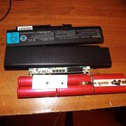
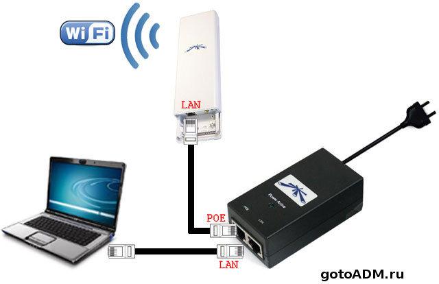
Порядок подключения устройства таков: сначала подключаете PoE и LAN кабели к инжектору (блоку питания) и ПК/ноутбуку, а затем включаете БП в сеть, как показано на рисунке ниже:
Заводские параметры для устройств Ubiquiti:
IP-адрес по умолчанию — 192.168.1.20
Логин по умолчанию — ubnt
Пароль по умолчанию — ubnt
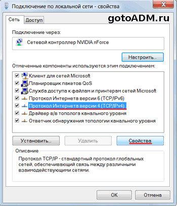
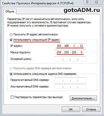
Для того, чтобы подключиться к устройству через браузер — необходимо задать сетевой карте адрес:
Initial Configuration for Transparent Bridge Mode
You can use
the Deployment Wizard to configure the basic
settings for transparent bridge mode on your Deep Discovery Web
Inspector appliance.
|
You can exit the Deployment Wizard at any time by clicking on another For considerations when deploying in an |
-
Go to Administration → Deployment Wizard.
The Welcome page
opens. - In the Deployment Mode section, select
Transparent bridge. - Click Next.
-
In the Network page, specify the following details:
Option
Description
Host
nameSpecify a host
name.Primary
DNS serverSpecify the IP
address of the DNS server. This is a required
setting.Secondary DNS server
Optionally,
specify the IP address for a secondary DNS server.Data
egress interfaceThis is a
read-only field and is pre-set to eth5.Data
ingress interfaceThis is a
read-only field and is pre-set to eth4.Management interface
This
is a read-only field and is pre-set to eth0.Mode
This is a read-only
field and is pre-set to static.IPv4
address, IPv4
netmask, and Default IPv4
gatewaySpecify the IPv4 network
settings.After you click
Finish, a dialog box opens asking if
you want to reboot the appliance. After you click
OK, the connection to the appliance
disconnects and the appliance reboots. After the appliance
restarts, the Log On page is
displayed. -
Click Next.
The Time page
opens. -
In the Time section,
configure the time and location settings for the Deep Discovery Web
Inspector appliance.Option
Description
NTP
serverEnter the NTP server IP
address.System time
zoneSet the
appropriate time zone by selecting the location closest
to the Deep Discovery Web
Inspector
appliance.Optionally, instead of
selecting a location, you can select
Etc and then choose the offset that
matches the location closest to the Deep Discovery Web
Inspector
appliance. -
Click Next.
The Summary page
opens. -
Review and verify the settings and then perform the
appropriate action:- If the settings are not as desired,
click on Prev and modify settings as
required. -
If the settings are verified, click on
Finish to save the configuration.After you click
Finish, a dialog box opens asking if
you want to reboot the appliance. After you click
OK, the connection to the appliance
disconnects and the appliance reboots. After the appliance
restarts, the Log On page is
displayed.If you do not want to reboot, you
can click Cancel instead of
OK. If you click
Cancel, the Summary page reopens.
If you exit the wizard before saving
settings, the configuration is not saved. - If the settings are not as desired,
Вы получаете
|
Отличный прием сигнала во всех комнатах Максимальная скорость интернета Перемещение по квартире без обрывов соединения (одна беспроводная сеть) |
Установка обрудования без прокладки новых сетевых кабелей Выское качество и стабильность устройcтв Симпатичный и стильный внешний вид |
Настройка точек доступа Ubiquiti AP
Наши специалисты произведут установку и настройку точек доступа Ubiquiti AP AC , эти точки доступа позволят вам получить быстрый интернет и широкий охват территории. Их основное преимущество в том, что они создают так называемую “бесшовную” сеть, эта технология объединяет все точки доступа Ubiquiti в одну WiFi сеть. Пользуясь интернетом вам больше не потребуется переключаться между разными беспроводными сетями, вы всегда будете подключены к одной единой беспроводной сети с высоким уровнем сигнала. Точки доступа Ubiquiti – идеальное решение для тех что хочет получить быстрый стабильный интернет в загородном доме или большой квартире!
Настройка беспроводного моста Ubiquiti NanoStation
Очень часто нужно настроить оборудование в режиме радио моста. Эта технология позволит передать беспроводной интернет сигнал из одного здания/помещения в другое. Преимущество заключается в том, что не потребуется прокладывать новый сетевой кабель, тк зачастую условия не позволяют это сделать. Так же следует отметить что беспроводной мост Ubiquiti может работать на десятки километров, передавая интернет сигнал даже в самые дальние уголки. Nano Station так же может использоваться как мощная точка доступа, которая является всепогодной и может быть установлена на улице. Во дворе загородного дома или на других территориях часто требуется пользоваться интернетом вне дома, UBNT NanoStation станет отличным помощником.
Настройка Ubiquiti UniFi AP Outdoor AC
Эта точка доступа имеет высокую мощность и создана для работы вне помещения 24×7. Она позволит охватить WiFi сигналом очень большую территорию вне дома, скорость при этом будет очень выской, а сигнал – стабильным ! Если вам нужен интернет вне дома, советуем присмотреться к решениям UBNT Outdoor.
Настройка камер видеонаблюдения UniFi Video G3
Американская компания так же предлагает устройства для видеонаблюдения. Это камеры серии G3 и видеорегистратор NVR. Наши специалисты отмечают довольно простую настройку камер ubiquiti и очень надежную работу данных камер. Они имеют высокое качество исполнения, удобную систему монтажа и гибкий функционал. Удаленный доступ к камерам UniFi так же настраивается, благодаря чему вы сможете получить доступ к вашим камерам из любого места.
Настройка сетевого регистратора UniFi NVR
Регистратор от UBNT работает в одной сети с камерами UniFi. Этот девайс хранит все видеозаписи с камер, а так же имеет дополнительные настройки для видеонаблюдения. Настройка регистратора и камер производится через сеть, утилиты для конфигурирования вы всегда можете найти на сайте производителя. При переходе на интерфейс NVR вы получите доступ ко всем сохраненным видеозаписям , а так же получите возможность к камерам от line.
Мы всегда готовы оказать помощь по настройке сетевого оборрудования Ubiquiti ! Выезд мастера по Москве и Московской области.
Преимущества
Система Ubiquiti Unifi AP отличается тем, что позволяет построить корпоративную беспроводную сеть с бесшовным роумингом. Благодаря такому принципу работы, все пользователи могут перемещаться в любую точку помещения в пределах действия Unifi. Некоторые ошибочно считают, что несколько Wi-Fi-роутеров могут заменить сеть с бесшовным роумингом, но такое суждение является полностью ошибочным. Дело в том, что единственная точка доступа, которая активируется при помощи самого простого домашнего роутера, не позволяет беспрепятственно переносить рабочий ноутбук, планшет в пределах здания. Постоянно требуется переключение на другую точку доступа, ввод нового ключа. При этом могут появляться технические сложности, задержки в рабочем процессе. Подобная проблема очень просто устраняется с помощью применения Unifi, которая является разработкой компании Ubiquiti.
Главное отличие описанной Unifi — применение бесплатного контроллера. Ещё до появления разработки компании Ubiquiti, стоимость внедрения корпоративной сети была очень высокой. Такую систему могли позволить себе только самые успешные компании. Например, установка системы от Cisco Aironet, более чем на 20 точек доступа, могла обойтись владельцам бизнеса в 10 тысяч долларов. При этом, основные затраты приходились на контроллер. Огромным преимуществом можно считать то, что Unifi controller распространяется среди покупателей системы бесплатно. При этом, такой программный модуль совместим с тремя наиболее распространёнными программными комплексами — Linux, Mac OC и, конечно, Windows.
Программный модуль Unifi controller показывает состояние всех точек доступа, которые расположены на плане здания. Кроме всего прочего, программный продукт предусматривает гостевой доступ. Суть его заключается в генерации временных ключей — их выдаёт администратор офиса посетителям, гостям. При этом, программа показывает статистику применения беспроводного доступа в интернет и список всех ассоциированных пользователей. Контроллер можно инсталлировать практически на любой персональный компьютер либо ноутбук. Главное условие — объём оперативной памяти должен соответствовать требованиям современного устройства и составлять хотя бы 2 Гб.

Можно выделить следующие технические особенности контроллера:
- Поддержка используемых на сегодняшний день типов шифрования;
- Построение до 4 виртуальных беспроводных сетей с различными параметрами;
- Наличие HotSpot, который имеет интегрированный PayPal, позволяет создавать талоны с ключами и создавать лимиты по времени для онлайн-доступа;
- Настройка скорости загрузки данных с возможностью её лимитирования;
- Автоинсталляция актуальной версии программы;
- Взаимодействие с сервисом Google Мaps, в котором можно отобразить точки доступа;
- Настройка в контроллере уделённых беспроводных сетей филиалов с целью управления.
Configuring Bridge Mode for Gateways
You can configure bridge mode with a single gateway or with a cluster. .
The bridge can work without an assigned IP address.
SmartDashboard helps you configure the topology for the bridge ports. There is a separate network or group object that represents the networks or subnets that connect to each port.
Configuring Single Gateway in Bridge Mode
|
Item |
Description |
|
|
1 and 2 |
Switches |
|
|
3 |
Security Gateway Firewall bridging Layer-2 traffic over the one IP address, with a subnet on each side using the same address. |
Before you begin, configure a dedicated management interface.
First you configure the . Then you define the bridge topology in SmartDashboard.
To define the bridge topology:
Use SmartDashboard to manually configure the topology for the bridge ports:
- If one of the bridge ports connects to the Internet, set the topology to External
- If the topology uses Anti-Spoofing, for the internal port (interface), make sure that you:
- Set the topology to Internal
- Select the Specific network that connects to the port
- If the topology does not use Anti-Spoofing, make sure that you disable Anti-Spoofing on the bridge port
Note — When you use Internet objects in a rule with a Security Gateway, make sure that the bridge interface is defined as External.
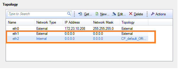
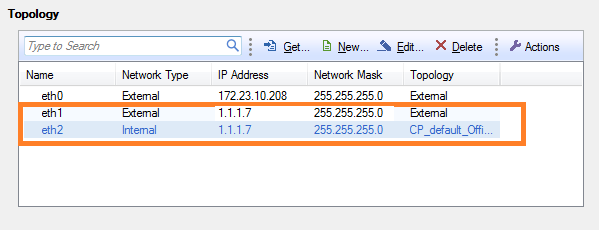
Configuring an IP Address for the Bridge
In a Security Gateway bridge deployment, you can configure an IP address for the bridge. The IP address of the bridge must be in the bridged subnet. The bridge IP address can be used for gateway management and access to the gateway portals.
When you assign an IP address to the bridge, the Topology window shows that both bridge ports have the same IP address as the bridge.
Configuring Gateway Cluster in Bridge Mode
You can configure cluster gateways for bridge mode in different deployments:
- Active/Standby mode
- Active/Active mode
|
Item |
Description |
|
|
1 and 2 |
Switches |
|
|
Security Gateway Firewall bridging Layer-2 traffic |
||
|
3 |
eth1 |
|
|
4 |
eth2 |
|
|
5 |
eth3 — the ClusterXL Sync interface |
Configuring Active/Standby Mode
This is the preferred mode in topologies that support it.
In Active-Standby mode, ClusterXL decides the cluster state. The standby member drops all packets. It does not pass any traffic, including STP/RSTP/MSTP. If there is a failover, the switches are updated by the Security Gateway to forward traffic to the new active member.
If you use this mode, it is best to disable STP/RSTP/MSTP on the adjacent switches.
To configure Active/Standby mode:
- .
- Run:
- Enter , to select Enable Check Point ClusterXL for Bridge Active/Standby.
- Confirm:
- Reboot the cluster member.
- Install Policy.
- Test the cluster state:
The output should be similar to:
Cluster Mode: High Availability (Active Up, Bridge Mode) with IGMP Membership
Number Unique Address Firewall State (*)
1 (local> 2.2.2.3 Active
2 2.2.2.2 Standby
Configuring Active/Active Mode
When you define a bridge interface on a Security Gateway cluster, Active/Active mode is activated by default.
Before you begin, install ClusterXL High Availability on a Gaia appliance or open server.
To configure Active/Active mode, do these steps on each member of the cluster:
- Configure dedicated management and Sync interfaces.
- Add a bridge interface, .
Do not configure an IP address on the newly created bridge interface.
- In SmartDashboard, add the cluster object:
- Open Topology of the cluster object.
- Get the cluster topology.
- Make sure the dedicated management and Sync interfaces are configured.
- Make sure the bridge interface and bridge ports are not in the topology.
Bridge port topology cannot be defined. It is external by default.
- Install Policy.
- Test the cluster state:
The output should be similar to:
- Make sure that cluster is configured as .
Confirming the High Availability Configuration
When you finish configuring Active/Active mode, the output for shows that the is . Make sure that the cluster is configured as High Availability in SmartDashboard.
To confirm the High Availability configuration:
- From SmartDashboard, double-click the cluster object.
The cluster window opens and shows the General Properties page.
- From the navigation tree, click ClusterXL.
- In the Cluster Mode section, make sure that High Availability is selected.
- Click OK.
Cluster Between Four Switches
You can configure a bridged cluster between four switches, in Active/Active mode.
Active/Standby mode is not supported.

|
Item |
Description |
|
1, 2, 3, 4 |
Switches |
|
Security Gateway Firewall bridging Layer-2 traffic |
|
|
5 |
eth1 |
|
6 |
eth2 |
|
7 |
eth3 — the ClusterXL Sync interface |
See also: Link Aggregation with ClusterXL in Layer-2
Routing and Bridges
Security Gateways with a bridge interface can support Layer 3 routing over non-bridged interfaces. If you configure a bridge interface with an IP address for one Security Gateway (not a cluster), the bridge functions as a regular Layer 3 interface. It participates in IP routing decisions on the gateway and supports Layer 3 routing.
- Cluster deployments do not support this configuration.
- You cannot configure the bridge to be the route gateway.
- One Security Gateway can support multiple bridge interfaces, but only one bridge can have an IP address.
- The Security Gateway cannot filter or transmit packets on a bridge interface that it inspected before (double-inspection).
Management over Bridge
The following diagram shows a sample topology:

|
Item |
Description |
|
1 |
Switch |
|
2 |
Router |
|
Security Gateway Firewall bridging Layer-2 traffic |
|
|
3 |
Management interface (inspects first packet) |
|
4 |
eth1 (inspects first packet again) |
|
5 |
eth2 |
|
6 |
Bridge interface — Management traffic drops |
|
7 |
Security Management Server |
When a Layer-3 management interface sends traffic through the firewall, the traffic is dropped because it cannot inspect the same packet again.
- The first packet is inspected and then goes from the management interface to the router.
- The router sends the packet to the bridge interface, and the firewall inspects the first packet again. The firewall concludes that this packet is a retransmission and then drops it.
Use the procedure for the applicable Security Gateway version.
Security Gateways R77.10 and Higher
This feature is supported in R77.10 and higher.
You can configure the Security Gateway to recognize that the first packet is from the management interface. The firewall makes sure that the MD5 hash of the packet that leaves the management interface and enters the bridge interface is the same. Other packets in this connection are handled by the bridge interface without using the router.
To enable management over the bridge:
- Edit .
If necessary, create this file.
- Add the appropriate line to the file:
- For IPv4 traffic —
- For IPv6 traffic —
is the IP address of the management interface.
- Reboot the Security Gateway.
Security Gateways R77 and Earlier
Incoming and outgoing traffic from a Layer-3 management interface is dropped if traversed over a bridge interface. You can make this traffic pass. Disable inspection on the management interface and disable local Anti-Spoofing.
Note: This removes inspection from the management interface and could compromise gateway security. If you are unsure whether your environment is safe to use this method, contact Check Point Solution Center.
To configure management over the bridge:
- Open and add:interface name
(Create this file if not found.)
Where the value (interface name) is the management interface name.
This excludes the management interface from SecureXL.
- Edit $.
(Create this file if not found.)
Add these lines:
interface name
Where the value (interface name) is the management interface name.
This disables local Anti-Spoofing and bridge routing, and excludes the management interface from security inspection.
- Reboot.
Introduction to Bridge Mode
Bridge Interfaces
Bridge interfaces connect two different interfaces (bridge ports). Bridging two interfaces causes every Ethernet frame that is received on one bridge port to be transmitted to the other port. Thus, the two bridge ports participate in the same Broadcast domain (which is different from router ports behavior).
Only two interfaces can be connected by a single Bridge interface. These two interfaces can then be thought of as a two-ports switch. Each port can be a physical, VLAN, or bond device.
Bridge interfaces can be configured on Check Point Security Gateway, and can be used for different deployments. The Firewall inspects every Ethernet frame that passes through the bridge.
Supported Software Blades: Gateway and Virtual Systems
These Software Blades support bridge mode (unless stated they do not) for single Security Gateway deployment, cluster with one switch in Active/Active and Active/Standby deployment, and cluster with four switches.
|
Supported Blade |
Supports Gateways in Bridge Mode |
Supports Virtual Systems in Bridge Mode |
|---|---|---|
|
Firewall |
Yes |
Yes |
|
IPS |
Yes |
Yes |
|
URL Filtering |
Yes |
Yes |
|
DLP |
Yes |
No |
|
Anti-Bot and Anti-Virus |
Yes |
Yes |
|
Application Control |
Yes |
Yes |
|
HTTPS Inspection |
Yes |
No |
|
Identity Awareness |
Yes |
No |
|
Threat Emulation |
Yes |
Yes |
|
QoS |
Yes |
No |
|
Client Authentication |
No |
No |
|
User Authentication |
No |
No |
Supported Software Blades: Management
Bridge-mode for a Security Management Server is supported only for Standalone configurations, and it supports all management Software Blades.
Unsupported for Bridge Mode
These features, Software Blades and deployments are not supported in Bridge Mode:
- Mobile Access Software Blade
- IPsec VPN Software Blade
- Full High Availability deployment
- NAT on Gateways
- Access to Portals from bridged networks, if the bridge does not have an assigned IP address
- Anti-Virus Traditional Mode
- Identity Awareness authentication other than AD Query (AD Query is the only supported authentication)
Supported Operating Systems
These operating systems support Bridge Mode configurations:
- Gaia and SecurePlatform — All
- IPSO — Only supports the Firewall Software Blade
For more about configuring Bridge Mode for an IPSO Security Gateway, see How To Setup a Bridge Mode Firewall on an IP Appliance with IPSO.
Table of Contents
Initial Steps
- Please begin by restoring the radio to factory defaults. This is critical, especially if you are troubleshooting a problem. If you need more information on how to do so, this video might help.
- With your Windows PC or Mac computer configured to the 192.168.1.x subnet, connect it to the radio using an Ethernet cable.
- Using a web browser, enter 192.168.1.20 as the URL to gain access to the radio’s management console.
- Enter ubnt as the administration account and ubnt as the password.
- This article bases its configuration instructions on the above, you will only need to change the elements mentioned, everything else should remain with its default values.
Configuration for Radio Labeled 192.168.1.2
| AC Devices | M Devices |
|
1. Choose the |Wireless| tab, and only change: Wireless Mode: Access Point PTP 2. Choose the |Network| tab, and only change:
3. Reboot or power cycle the modem off and on before using this link for the first time. |
1. Choose the |Wireless| tab, and only change:
2. Choose the |Network| tab, and only change:
3. Reboot or power cycle the modem off and on before using this link for the first time. |
Configuration for Radio Labeled 192.168.1.3
| AC Devices | M Devices |
|
1. Repeat steps 1 through 4 from the section.2. Choose the |Wireless| tab, and only change: Wireless Mode: Station PTP 3. Choose the |Network| tab, and only change:
4. Reboot or power cycle the modem off and on before using this link for the first time. |
1. Repeat steps 1 through 4 from the section.2. Choose the |Wireless| tab, and only change:
3. Choose the |Network| tab, and only change:
4. Click Apply. 5. Reboot or power cycle the modem off and on before using this link for the first time. |
User Tips
- Select the correct cable. Use Ubiquiti ToughCable Pro shielded twisted pair data cable between your Power over Ethernet adapter and your radio. If the radio is being co-located in an area with a VHF pager, FM or TV broadcast transmitter, use Ubiquiti ToughCable Carrier cable. See our TOUGHCable Datasheet for more information.
-
Secure the radios. Modify the default administration account name and password now. From the web management console:
- Go to System > System Accounts
- Administrative Username
- Hover over icon to the right, Change Password and modify it (for M devices, for AC devices simply Change Password).
- Click the Change button. Then click the Apply button. (For M devices, for AC devices simply click the Save button)
- Secure the wireless signal. Encrypt the wireless connection. From the web management console:
- Go to Wireless > Wireless Security > Security > WPA2-AES
- WPA Preshared Key: enter a strong password
- Click the Change button. Then click the Apply button. (For M devices, for AC devices simply click the Save button)
In the above, the block of equipment after the Switch could be replaced with anything desired to bridge, including a SOHO Wi-Fi router, for example. This radio configuration acts like a simple Cat-5 cable.
|
NOTE: These instructions (for M devices) can also be found in video format here. |