Catalyst 2960 and 2960-S Software Configuration Guide, 12.253SE1
Содержание:
- Настройка ssh cisco
- Оборудование и схема сети
- Using Interface Configuration Mode
- Configuring EtherChannels and Link-State Tracking
- Шаг 2. Настройка ГиперТерминала
- Using the show platform forward Command
- Preventing Switch Stack Problems
- Preventing Autonegotiation Mismatches
- Recovering from a Software Failure
- Команды для конфигурирования CISCO
- Configuring the System MTU
- Шаг 3. Общие принципы настройки оборудования Cisco
- Шаг 1. Подключение оборудования Cisco
- Configuring Layer 3 SVIs
- SFP Module Security and Identification
- Troubleshooting
- Recovering from a Lost or Forgotten Password
- Understanding Stacks
Настройка ssh cisco
И так давайте рассмотрим как производится настройка ssh cisco, я буду это показывать на примере симулятора Cisco packet tracer, но отличий от реального оборудования вы не обнаружите. До этого мы уже создали локального пользователя net_admin. Давайте включим ssh соединение и дадим ему возможность подключаться через него.
Заходим в режим конфигурирования и вводим.
config t line vty 0 5
vty означает виртуальный терминал

Как включить ssh в Cisco на примере Cisco 2960+48TC-S-01
Дальше включаем ssh для входящего трафика
Как включить ssh в Cisco на примере Cisco 2960+48TC-S-02
Говорим что авторизация будет через локальное хранилище учетных записей, выходим и сохраняем настройки.
login local end wr mem
Как включить ssh в Cisco на примере Cisco 2960+48TC-S-03
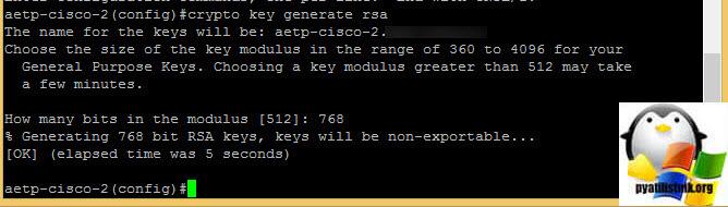
так же может потребоваться сгенерировать ключ шифрования, бывают случаи, что вы все включили, а ssh соединение не проходит, и происходит это из за того, что нет ключа, давайте покажу как его сгенерировать в ручную.
crypto key generate rsa
На вопрос какой размер ключа, я ответил 768
Посмотреть сгенерированный ssh ключ, можно командой:
show crypto key mypubkey rsa
Посмотреть текущие ssh соединения можно командой:
show ssh
Обратите внимание, что тут видно версию ssh, у меня это ssh 2.0

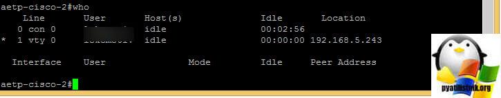
Еще есть полезная команда who, она показывает и консольные соединения и еще Ip адреса откуда идет подключение.
Безопасность ssh соединения Cisco
Очень важным моментом настройки ssh cisco, является еще и безопасность, все конечно здорово, что трафик шифруется, но нам нужно желательно изменить порт подключения на нестандартный и ограничить количество попыток соединения, ниже этим и займемся.
Для начала давайте ограничим количество попыток соединения по ssh протоколу, пишем:
ip ssh authentication-retries 3
Сразу включим занесение всех событий по терминалу в журнал. Это даст информацию кто и с каких ip адресов пытался подключиться. Если вы вдруг обнаружите большое количество сообщений, в которых идет попытка залогиниться с ошибкой, то у вас подбирают пароль.
ip ssh logging events
В таких случаях, да и вообще в принципе настройка ssh cisco всегда должна быть на нестандартный порт, например 2233
ip ssh port 2233 rotary 1
Хоть rotary и дает возможность производить подключение по ssh по нестандартному порту, 22 порт он не выключает, сделать это нужно в ручную, с помощью
access-list
ip access-list extended ssh_22
deny tcp any host 192.168.2.1 eq 22
Применим access-list к внешнему интерфейсу маршрутизатора
interface FastEthernet0/1
description uplink
ip address 192.168.2.1 255.255.255.0
ip access-group ssh_22
ip nat outside
Теперь давайте назначим созданный rotary на виртуальный терминал vty
line vty 0 4 rotary 1
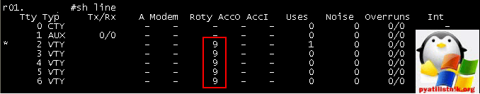
Если хотите, то можете вообще указать отдельному vty, но учтите, что если терминал будет занят, то подключиться у другого не получиться.
line vty 1 rotary 1
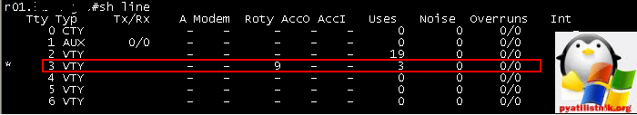
Если стоит задача ограничить ssh подключение двумя сессиями, то вот команда:
ip ssh maxstartups 2
Ограничение времени timeoutá (по дефолту 300 секунд). SSH сервер прерывает соединение, если не передаются никакие данные в течение этого времени ожидания.
ip ssh time-out 120
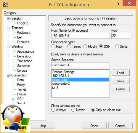
Для того, чтобы вам подключиться по ssh соединению, нужно скачать любую программу для этого, у меня это putty, во вкладке session в поле Host name я ввожу Ip адрес устройства к которому я буду подключаться, протокол ставлю ssh и порт 22, нажимаю Open.
Ноя 18, 2014 00:20
-
Последние записи
- Программа 1cv8c.exe версии прекратила взаимодействие с Windows
- Как изменить имя компьютера Windows 10, за минуту
- Подключение было запрещено, учетная запись пользователя не имеет прав
- Windows Identity Foundation ошибка 0x80096002
- Duplicate key was found при установке ManageEngine ServiceDesk 10508
Оборудование и схема сети
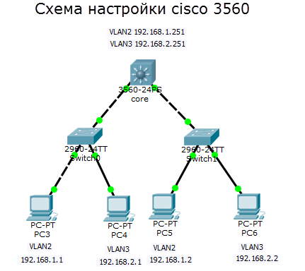
Предположим, что у меня коммутатор 3 уровня cisco 3560 24 порта, он выглядит как то вот так.
Он будет маршрутизировать трафик между vlan в моей локальной сети, и к нему допустим будут подключены 3 коммутатора 2 уровня модели OSI, уровня доступа, коммутаторы cisco 2960, а сам cisco 3560 будет выступать в качестве коммутатора уровня распределения. Напомню, что на втором уровне коммутируется трафик на основе mac адресов. Уровень доступа это куда подключаются конечные устройства, в нашем случае компьютеры, сервера или принтеры.. Ниже схема.
Что такое коммутатор второго уровня
Коммутатор второго уровня это железка работающая на втором уровне сетевой модели OSI
- Коммутирует трафик на основе мак адресов
- Используется в качестве уровня доступа
- Служит для первичного сегментирования локальных сетей
- Самая маленькая стоимость за порт/пользователь
В технической документации коммутатор второго уровня обозначает в виде вот такого значка
Что такое коммутатор третьего уровня
Коммутатор третьего уровня это железка работающая на третьем уровне модели OSI умеющая:
- IP маршрутизация
- Агрегирование коммутаторов уровня доступа
- Использование в качестве коммутаторов уровня распределения
- Высокая производительность
В технической документации коммутатор третьего уровня обозначает в виде вот такого значка
Помогать мне будет в создании тестового стенда программа симулятор сети, Cisco packet tracer 6.2. Скачать Cisco packet tracer 6.2, можно тут. Вот более детальная схема моего тестового полигона. В качестве ядра у меня cisco catalyst 3560, на нем два vlan: 2 и 3, со статическими ip адресами VLAN2 192.168.1.251 и VLAN3 192.168.2.251. Ниже два коммутатора уровня доступа, используются для организации VLAN и как аплинки. В локальной сети есть 4 компьютера, по два в каждом vlan. Нужно чтобы компьютер PC3 из vlan2 мог пинговать компьютер PC5 из vlan3.
С целью мы определились можно приступать. Напоминать, про то что такое vlan я не буду можете почитать тут.
Using Interface Configuration Mode
The switch supports these interface types:
- Physical ports—switch ports
- VLANs—switch virtual interfaces
- Port channels—EtherChannel interfaces
You can also configure a range of interfaces (see the ).
To configure a physical interface (port) on a Catalyst 2960 switch or a Catalyst 2960-S switch running the LAN Lite image, specify the interface type, module number, and switch port number, and enter interface configuration mode. To configure a port on a Catalyst 2960-S switch running the LAN base image (supporting stacking), specify the interface type, stack member number, module number, and switch port number, and enter interface configuration mode.
- Type —Port types depend on those supported on the switch. Possible types are: Fast Ethernet (fastethernet or fa) for 10/100 Mb/s Ethernet, Gigabit Ethernet (gigabitethernet or gi) for 10/100/1000 Mb/s Ethernet ports, 10-Gigabit Ethernet (tengigabitethernet or te) for 10,000 Mb/s, or small form-factor pluggable (SFP) module Gigabit Ethernet interfaces.
- Stack member number —The number that identifies the switch within the stack. The switch number range is 1 to 4 and is assigned the first time the switch initializes. The default switch number, before it is integrated into a switch stack, is 1. When a switch has been assigned a stack member number, it keeps that number until another is assigned to it.
- Module number — The module or slot number on the switch (always 0).
- Port number—The interface number on the switch. The port numbers always begin at 1, starting with the far left port when facing the front of the switch, for example, gigabitethernet1/0/1. For a switch with 10/100/1000 ports and SFP module ports, SFP module ports are numbered consecutively following the 10/100/1000 ports.
You can identify physical interfaces by looking at the switch. You can also use the show privileged EXEC commands to display information about a specific interface or all the interfaces. The remainder of this chapter primarily provides physical interface configuration procedures.
These examples identify interfaces on a Catalyst 2960-S switch running the LAN base image:
To configure 10/100/1000 port 4 on a standalone switch, enter this command:
This example identifies an interface on a Catalyst 2960 switch or a Catalyst 2960-S switch running the LAN Lite image:
To configure 10/100/1000 port 4, enter this command:
Note Configuration examples and outputs in this book might not be specific to your switch, particularly regarding the presence of a stack member number.
Configuring EtherChannels and Link-State Tracking
Note To use link-state tracking, the switch must be running the LAN Base image.
Note This chapter describes how to configure EtherChannels on the Catalyst 2960 and 2960-S switches. EtherChannel provides fault-tolerant high-speed links between switches, routers, and servers. You can use it to increase the bandwidth between the wiring closets and the data center, and you can deploy it anywhere in the network where bottlenecks are likely to occur. EtherChannel provides automatic recovery for the loss of a link by redistributing the load across the remaining links. If a link fails, EtherChannel redirects traffic from the failed link to the remaining links in the channel without intervention. This chapter also describes how to configure link-state tracking. Unless otherwise noted, the term switch refers to a standalone switch and to a switch stack.Stacking is supported only on Catalyst 2960-S switches running the LAN base image.
Note For complete syntax and usage information for the commands used in this chapter, see the command reference for this release.
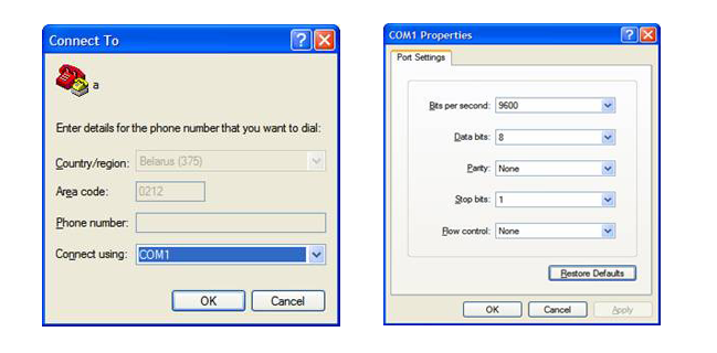
Шаг 2. Настройка ГиперТерминала
Следующей проблемой, с которой вам придется столкнуться – это отсутствие ГиперТерминала (HyperTerminal) в Windows 7/8.
Решением вопроса является копирование папки HyperTerminal c Windows XP (месторасположение каталога – Program Files) в любой удобный каталог Windows 7/8.
Для запуска программы используется файл hypertrm.exe, который можно найти в той же папке.
Либо использовать программу Putty, которую помимо подключения к Cisco-оборудованию можно использовать для подключения к серверам, маршрутизаторам, пр. с помощью SSH-подключения.
Переходим к подключению. На передней панели коммутатора ищем разъем RJ-45 с подписью «Console», и подключаем кабель.
Включаем питание коммутатора.
Заходим на компьютере в HyperTerminal, выбираем интерфейс разъема (COM1), скорость порта – 9600 Б/с, на все дальнейшие вопросы даем отрицательный ответ («No»).
Using the show platform forward Command
The output from the show platform forward privileged EXEC command provides some useful information about the forwarding results if a packet entering an interface is sent through the system. Depending upon the parameters entered about the packet, the output provides lookup table results and port maps used to calculate forwarding destinations, bitmaps, and egress information.
Note For more syntax and usage information for the show platform forward command, see the switch command reference for this release.
Most of the information in the output from the command is useful mainly for technical support personnel, who have access to detailed information about the switch application-specific integrated circuits (ASICs). However, packet forwarding information can also be helpful in troubleshooting.
This is an example of the output from the show platform forward command on port 1 in VLAN 5 when the packet entering that port is addressed to unknown MAC addresses. The packet should be flooded to all other ports in VLAN 5.
This is an example of the output when the packet coming in on port 1 in VLAN 5 is sent to an address already learned on the VLAN on another port. It should be forwarded from the port on which the address was learned.
Preventing Switch Stack Problems
Note ● Make sure that the switches that you add to or remove from the switch stack are powered off. For all powering considerations in switch stacks, see the “Switch Installation” chapter in the hardware installation guide.
- After adding or removing stack members, make sure that the switch stack is operating at full bandwidth (32 Gb/s). Press the Mode button on a stack member until the Stack mode LED is on. The last two port LEDs on the switch should be green. Depending on the switch model, the last two ports are either 10/100/1000 ports or small form-factor pluggable (SFP) module ports. If one or both of the last two port LEDs are not green, the stack is not operating at full bandwidth.
- We recommend using only one CLI session when managing the switch stack. Be careful when using multiple CLI sessions to the stack master. Commands that you enter in one session are not displayed in the other sessions. Therefore, it is possible that you might not be able to identify the session from which you entered a command.
- Manually assigning stack member numbers according to the placement of the switches in the stack can make it easier to remotely troubleshoot the switch stack. However, you need to remember that the switches have manually assigned numbers if you add, remove, or rearrange switches later. Use the switch current-stack-member-number renumber new-stack-member-number global configuration command to manually assign a stack member number. For more information about stack member numbers, see the .
If you replace a stack member with an identical model, the new switch functions with the exact same configuration as the replaced switch. This is also assuming the new switch is using the same member number as the replaced switch.
Removing powered-on stack members causes the switch stack to divide (partition) into two or more switch stacks, each with the same configuration. If you want the switch stacks to remain separate, change the IP address or addresses of the newly created switch stacks. To recover from a partitioned switch stack:
1. Power off the newly created switch stacks.
2. Reconnect them to the original switch stack through their StackWise ports.
3. Power on the switches.
Preventing Autonegotiation Mismatches
The IEEE 802.3ab autonegotiation protocol manages the switch settings for speed (10 Mb/s, 100 Mb/s, and 1000 Mb/s, excluding SFP module ports) and duplex (half or full). There are situations when this protocol can incorrectly align these settings, reducing performance. A mismatch occurs under these circumstances:
- A manually set speed or duplex parameter is different from the manually set speed or duplex parameter on the connected port.
- A port is set to autonegotiate, and the connected port is set to full duplex with no autonegotiation.
To maximize switch performance and ensure a link, follow one of these guidelines when changing the settings for duplex and speed:
- Let both ports autonegotiate both speed and duplex.
- Manually set the speed and duplex parameters for the ports on both ends of the connection.
Note If a remote device does not autonegotiate, configure the duplex settings on the two ports to match. The speed parameter can adjust itself even if the connected port does not autonegotiate.
Recovering from a Software Failure
Switch software can be corrupted during an upgrade, by downloading the wrong file to the switch, and by deleting the image file. In all of these cases, the switch does not pass the power-on self-test (POST), and there is no connectivity.
This procedure uses the Xmodem Protocol to recover from a corrupt or wrong image file. There are many software packages that support the Xmodem Protocol, and this procedure is largely dependent on the emulation software that you are using.
This recovery procedure requires that you have physical access to the switch.
Step 1 From your PC, download the software image tar file ( image_filename.tar) from Cisco.com.
The Cisco IOS image is stored as a bin file in a directory in the tar file. For information about locating the software image files on Cisco.com, see the release notes.
Step 2 Extract the bin file from the tar file.
- If you are using Windows, use a zip program that can read a tar file. Use the zip program to navigate to and extract the bin file.
- If you are using UNIX, follow these steps:
1. Display the contents of the tar file by using the tar -tvf image_filename.tar > UNIX command.
2. Locate the bin file, and extract it by using the tar -xvf image_filename.tar > image_filename.bin > UNIX command.
3. Verify that the bin file was extracted by using the ls -l image_filename.bin > UNIX command.
Step 3 Connect your PC with terminal-emulation software supporting the Xmodem Protocol to the switch console port.
Step 4 Set the line speed on the emulation software to 9600 baud.
Step 5 Unplug the switch power cord.
Step 6 Press the Mode button and at the same time, reconnect the power cord to the switch.
You can release the Mode button a second or two after the LED above port 1 goes off. Several lines of information about the software appear along with instructions:
Step 7 Initialize the flash file system:
Step 8 If you had set the console port speed to anything other than 9600, it has been reset to that particular speed. Change the emulation software line speed to match that of the switch console port.
Step 9 Load any helper files:
Step 10 Start the file transfer by using the Xmodem Protocol.
Step 11 After the Xmodem request appears, use the appropriate command on the terminal-emulation software to start the transfer and to copy the software image into flash memory.
Step 12 Boot the newly downloaded Cisco IOS image.
Step 13 Use the archive download-sw privileged EXEC command to download the software image to the switch or to the switch stack.
Step 14 Use the reload privileged EXEC command to restart the switch and to verify that the new software image is operating properly.
Step 15 Delete the flash: image_filename.bin file from the switch.
Команды для конфигурирования CISCO
Шпаргалка для себя и для студентов
Установка пароля для консоли
R1(config)#line console 0
R1(config-line)#password cisco
R1(config-line)#login
Установка пароля для telnet
R1(config)#line vty 0 4
R1(config-line)#password cisco
R1(config-line)#login
Удаление консольного пароля
router(config)#line console 0
router(config-line)#no login
router(config-line)#no password
Удаление пароля Secret
router(config)#no enable secret
Проверка параметра Register
router>enable
router#show version
Задание адреса-маски и административное включение интерфейса
R1(config)#interface Serial0/0/0
R1(config-if)#ip address 192.168.2.1 255.255.255.0
Административное выключение интерфейса маршрутизатора
router(config)#int s0/0
router(config-if)#shutdown
Включение интерфейса Serial
router#configure terminal
router(config)#interface s0/0
router(config-if)#no shutdownУстановка тактовой частоты для интерфейса Serial
router(config-if)#clock rate 64000
Проверка интерфейса Serial
router(config)#show interfaces s0/0
Добавить статическую запись в таблицу маршрутизации
Router(config)#ip route 10.10.10.0 255.255.255.0 {ip-address | exit-interface }
Посмотреть таблицу маршрутизации
R1#show ip route
Посмотреть интерфейсы
R1#show interfaces
Посмотреть интерфейсы и их статистику в табличном виде
R1#show ip interface brief
Посмотреть соседей устройства:
Router#show cdp neighbors
Router#show cdp neighbors detail
Глобальное выключение CDP (cisco discovery protocol):
Router(config)#no cdp runВыключение CDP (cisco discovery protocol) на интерфейсе:
Router(config-if)#no cdp enable
Статус DTE/DCE
router#show controllers s0/0
Сохранение конфигурации
router#copy running-config startup-config
Загрузка файла (например IOS) с TFTP сервера
R#copy tftp flash:
Резервное копирование Startup конфига на TFTP
router#copy startup-config tftp
Сохранение Running конфига
router#write memory
router#copy run st
Удаление конфигурации NVRAM
router#write erase
Проверка конфигурации NVRAM
router#show startup-config
Посмотреть таблицу MAC адресов свитча
show mac-address-table
Статически прописать MAC адрес в таблицу адресов свитча
#mac-address-table static MAC address vlan {1-4096, ALL} interface interface-id command
Создать VLAN
S1(config)#vlan 20
S1(config-vlan)#name students
Создаем интерфейс для управления VLAN
S1(config)#interface vlan 20
S1(config-if)#ip address 10.2.2.1 255.255.255.0
S1(config-if)#no shutdown
Назначить порт для доступа к VLAN
S1(config)#interface fa0/18
S1(config-if)#switchport mode access
S1(config-if)#switchport access vlan 20
Назначить порт для транка Cisco Dynamic Trunking protocol
S1(config)#interface fa0/18
или S1(config-if)#switchport mode trunk
ли S1(config-if)#switchport mode dynamic auto
или S1(config-if)#switchport mode dynamic desirable
или S1(config-if)#switchport mode nonegotiate
какие vlan пропускать через trunk
S1(config-if)#switchport trunk allowed vlan 18 (можно указывать диапазоны или all)
Переключиться обратно из trunk в режим доступа
S1(config-if)#no switchport trunk allowed vlan
S1(config-if)#no switchport trunk native vlan
S1(config-if)#switchport mode access
Разрешить трафик местного (native) VLAN через порт транка
S1(config)#interface fa0/18
S1(config-if)#switchport mode trunk
S1(config-if)#switchport trunk native vlan 18
S1#show interfaces fa0/18 switchport
Посмотреть статистику VLAN
или show vlan brief
или show vlan id 20
или show vlan name students
или show vlan summary
Посмотреть статистику портов свитча
show interfaces vlan 20
show interfaces fa0/18 switchport
Назначить шлюз по умолчанию
S1(config)#ip default gateway 1.2.3.4
Включить протокол динамической маршрутизации
R1(config)#router протокол (rip, eigrp и т.д.)
R1(config-router)#network network_number
R1(config-if)#bandwidth 64
R1(config-router)#passive-interface s 0/0/0 Выключить динамическую маршрутизацию на интерфейсе
или
R1(config-router)#passive-interface default Выключить динамическую маршрутизацию на всех интерфейсах
а потом на некоторых включить:
R1(config-router)#no passive-interface s 0/0/0
Configuring the System MTU
The default maximum transmission unit (MTU) size for frames received and transmitted on all interfaces is 1500 bytes. You can increase the MTU size for all interfaces operating at 10 or 100 Mb/s by using the system mtu global configuration command. You can increase the MTU size to support jumbo frames on all Gigabit Ethernet interfaces by using the system mtu jumbo global configuration command.
Gigabit Ethernet ports are not affected by the system mtu command; 10/100 ports are not affected by the system mtu jumbo command. If you do not configure the system mtu jumbo command, the setting of the system mtu command applies to all Gigabit Ethernet interfaces.
You cannot set the MTU size for an individual interface; you set it for all 10/100 or all Gigabit Ethernet interfaces. When you change the system or jumbo MTU size, you must reset the switch before the new configuration takes effect.
Frames sizes that can be received by the switch CPU are limited to 1998 bytes, no matter what value was entered with the system mtu or system mtu jumbo commands. Although frames that are forwarded are typically not received by the CPU, in some cases, packets are sent to the CPU, such as traffic sent to control traffic, SNMP, or Telnet.
Note If Layer 2 Gigabit Ethernet interfaces are configured to accept frames greater than the 10/100 interfaces, jumbo frames received on a Layer 2 Gigabit Ethernet interface and sent on a Layer 2 10/100 interface are dropped.
Beginning in privileged EXEC mode, follow these steps to change MTU size for all 10/100 or Gigabit Ethernet interfaces:
If you enter a value that is outside the allowed range for the specific type of interface, the value is not accepted.
Once the switch reloads, you can verify your settings by entering the show system mtu privileged EXEC command.
This example shows how to set the maximum packet size for a Gigabit Ethernet port to 1800 bytes:
This example shows the response when you try to set Gigabit Ethernet interfaces to an out-of-range number:
Шаг 3. Общие принципы настройки оборудования Cisco
В целях безопасности на коммутаторах Cisco доступно 2 режима ввода команд: пользовательский режим для проверки состояния коммутатора и привилегированный режим (аналог пользователя root в UNIX или администратора в Windows) для изменения конфигурации коммутатора.
Для пользователей, привыкших работать в UNIX-системах, понять в каком режиме они работают не составит труда.
Для пользователей, работающих в Windows дадим пояснение, — если строка перед командной начинается с символа «#», вы в привилегированном режиме.
То же самое касается ввода пароля, как и в UNIX-системах, пароль, который вводит пользователь не отображается на экране.
Для перехода в привилегированный режим служит команда «enable», без кавычек, а для выхода «disable».
Приступим к первичной настройке коммутатора. При первой загрузке устройства мастер установки предложит выполнить пошаговую настройку, отказываемся от этого шага:
Continue with configuration dialog? [yes/no]: no
После чего оказываемся в пользовательский режиме:
Switch>
Переходим в привилегированный режим, пароль по умолчанию, как правило, отсутствует, поэтому ничего не вводим, а нажимаем «Enter».
Switch> enable
Password:
Switch#
Для задания настроек, касающихся всего коммутатора (задание имени коммутатора, IP-адреса, указание сервера синхронизации времени, пр), используется режим глобальной конфигурации, для настройки отдельных интерфейсов существует режим конфигурации интерфейса.
Шаг 1. Подключение оборудования Cisco
Настройка оборудования Cisco весьма специфична и несколько отличается от оборудования других производителей.
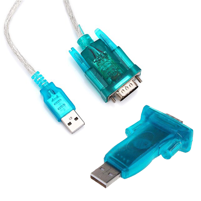
Например, для выполнения первичных настроек коммутаторов компании Cisco, нам потребуется фирменный плоский кабель RJ-45 – RS-232 голубого цвета (идет в комплекте с оборудованием) и наличие COM-порта на компьютере, с которого будет производиться настройка.

Большинство материнских плат современных настольных и портативных компьютеров не имеют соответствующего разъема. В таком случае необходимо искать переходник.
В последнее время Cisco стала комплектовать оборудование разъемом Mini—USB для консоли.
Для настройки устройства через порт Mini—USB, необходимо скачать cisco usb console driver.
Configuring Layer 3 SVIs
Note Only switches running the LAN base image support Layer 3 SVIs for static routing.
You should configure SVIs for any VLANs for which you want to route traffic. SVIs are created when you enter a VLAN ID following the interface vlan global configuration command. To delete an SVI, use the no interface vlan global configuration command. You cannot delete VLAN 1.
Note When you create an SVI, it does not become active until you associate it with a physical port. For information about assigning Layer 2 ports to VLANs, see
A Layer 3 switch can have an IP address assigned to each SVI, but the switch supports static routing on 16 SVIs. All Layer 3 interfaces require an IP address to route traffic. This procedure shows how to configure an interface as a Layer 3 interface and how to assign an IP address to an interface.
Beginning in privileged EXEC mode, follow these steps to configure a Layer 3 SVI:
To remove an IP address from an SVI, use the no ip address interface configuration command.
This example shows how to configure a Layer 3 SVI and to assign it an IP address:
SFP Module Security and Identification
Cisco small form-factor pluggable (SFP) modules have a serial EEPROM that contains the module serial number, the vendor name and ID, a unique security code, and cyclic redundancy check (CRC). When an SFP module is inserted in the switch, the switch software reads the EEPROM to verify the serial number, vendor name and vendor ID, and recompute the security code and CRC. If the serial number, the vendor name or vendor ID, the security code, or CRC is invalid, the software generates a security error message and places the interface in an error-disabled state.
Note The security error message references the GBIC_SECURITY facility. The switch supports SFP modules and does not support GBIC modules. Although the error message text refers to GBIC interfaces and modules, the security messages actually refer to the SFP modules and module interfaces. For more information about error messages, see the system message guide for this release.
If you are using a non-Cisco SFP module, remove the SFP module from the switch, and replace it with a Cisco module. After inserting a Cisco SFP module, use the errdisable recovery cause gbic-invalid global configuration command to verify the port status, and enter a time interval for recovering from the error-disabled state. After the elapsed interval, the switch brings the interface out of the error-disabled state and retries the operation. For more information about the errdisable recovery command, see the command reference for this release.
Troubleshooting
This chapter describes how to identify and resolve software problems related to the Cisco IOS software on the Catalyst 2960 and 2960-S switches. Depending on the nature of the problem, you can use the command-line interface (CLI), the device manager, or Network Assistant to identify and solve problems.
Unless otherwise noted, the term switch refers to a standalone switch and to a switch stack.
Note Stacking is supported only on Catalyst 2960-S switches running the LAN base image.
Additional troubleshooting information, such as LED descriptions, is provided in the hardware installation guide.
Note For complete syntax and usage information for the commands used in this chapter, see the command reference for this release and the Cisco IOS Commands Master List, Release 12.2 from the Cisco.com page under Documentation > Cisco IOS Software > 12.2 Mainline > Command References.
This chapter consists of these sections:
Note Recovery procedures require that you have physical access to the switch.
Recovering from a Lost or Forgotten Password
The default configuration for the switch allows an end user with physical access to the switch to recover from a lost password by interrupting the boot process during power-on and by entering a new password. These recovery procedures require that you have physical access to the switch.
Note On these switches, a system administrator can disable some of the functionality of this feature by allowing an end user to reset a password only by agreeing to return to the default configuration. If you are an end user trying to reset a password when password recovery has been disabled, a status message shows this during the recovery process.
These sections describes how to recover a forgotten or lost switch password:
You enable or disable password recovery by using the service password-recovery global configuration command. When you enter the service password-recovery or no service password-recovery command on the stack master, it is propagated throughout the stack and applied to all switches in the stack.
Note Stacking is supported only on Catalyst 2960-S switches running the LAN base image.
Follow the steps in this procedure if you have forgotten or lost the switch password.
Step 1 Connect a terminal or PC with terminal-emulation software to the switch console port.
Step 2 Set the line speed on the emulation software to 9600 baud.
Step 3 Power off the standalone switch or the entire switch stack.
Step 4 Reconnect the power cord to the standalone switch or the stack master and, within 15 seconds, press the Mode button while the System LED is still flashing green. Continue pressing the Mode button until the System LED turns briefly amber and then solid green; then release the Mode button.
Several lines of information about the software appear with instructions, informing you if the password recovery procedure has been disabled or not.
If you see a message that begins with this:
go to the , and follow the steps.
If you see a message that begins with this:
go to the , and follow the steps.
Step 5 After recovering the password, reload the standalone switch or the stack master:
Step 6 Power on the rest of the switch stack.
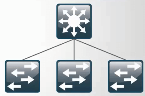
Understanding Stacks
A switch stack is a set of up to four Catalyst 2960-S switches connected through their stack ports. One of the switches controls the operation of the stack and is called the stack master. The stack master and the other switches in the stack are stack members. Layer 2 protocol presents the entire switch stack as a single entity to the network.
Note A switch stack is different from a switch cluster. A switch cluster is a set of switches connected through their LAN ports, such as the 10/100/1000 ports. For more information about how switch stacks differ from switch clusters, see the “Planning and Creating Clusters” chapter in the Getting Started with Cisco Network Assistant on Cisco.com.
The master is the single point of stack-wide management. From the master, you configure:
- System-level (global) features that apply to all members
- Interface-level features for each member
If the stack master is running the cryptographic version (that is, supports encryption) of the software, the encryption features are available.
Every member is uniquely identified by its own stack member number.
All members are eligible masters. If the master becomes unavailable, the remaining members elect a new master from among themselves. One of the factors is the stack member priority value. The switch with the highest stack-member priority-value becomes the master.
The system-level features supported on the master are supported on the entire stack.
The master contains the saved and running configuration files for the stack. The configuration files include the system-level settings for the stack and the interface-level settings for each member. Each member has a current copy of these files for back-up purposes.
You manage the stack through a single IP address. The IP address is a system-level setting and is not specific to the master or to any other member. You can manage the stack through the same IP address even if you remove the master or any other member from the stack.
You can use these methods to manage stacks:
- Network Assistant (available on Cisco.com)
- Command-line interface (CLI) over a serial connection to the console port of any member
- A network management application through the Simple Network Management Protocol (SNMP)
Note Use SNMP to manage network features across the stack that are defined by supported MIBs. The switch does not support MIBs to manage stacking-specific features such as stack membership and election.
CiscoWorks network management software
To manage stacks, you should understand:
These concepts on stack formations:
–
–
These concepts on stack and member configurations:
–
–
–
–
–
–
–
–
–
–
–
–
–
This concept on stack topology changes:
–