Кроссовер кабель распиновка
Содержание:
- Overview
- What Is Cross-Over Cable
- Примечания
- Crossover cable pinouts
- Automatic crossover
- Кроссировочный провод
- Монтаж, подключение интернет розетки RJ-1145 Распиновка Цветовые схемы обжима кабеля витых пар
- Automatic crossover
- Automatic crossover
- Concept
- External links
- Why You Probably Dont Need A Cross-Over Cable
- Making The Cable
- Распиновка выводов перекрестного кабеля
Overview
Before you begin creating your Patch Cable or Network Crossover Cable, it’s important to point out that the method outlined here is only one method. It is by no means the only or best method. Also, make sure you have all the necessary tools and materials before you begin. You will need a length of CAT cable, several RJ-45 connectors, and a crimp tool.
- Most crimp tools have two blades: one designed to cut completely through a cable and the other designed to strip the cable jacket/insulation. Using the latter blade, strip the cable jacket/insulation back about an inch, so all the wires inside are exposed. Be careful not to cut the inside wires when stripping the cable’s insulation.
- With the jacket/insulation removed, you’ll find eight wires and a string inside the CAT 5 cable. Cut the string off, and untwist the wires back to within one-eighth inch of the jacket.
- Fan the wires out from left to right in the order they are to be crimped. The crimping order depends on the type of cable you are making. For this guide, we will be wiring the cable to CAT 5 EIA 568B specifications. This is the configuration for a standard CAT 5 patch cable (See Table 1 and Figure A).
- Grasp the wires firmly between your fingers and flatten them to remove their curliness. The wires must lay flat and together, aligned as closely as possible. Try not to get them out of order.
- While holding them firmly, cut off about a half-inch of the exposed wires, so they are all the same length.
- Slide the RJ-45 connector onto the wires, making sure the wires stay lined up. The connector has eight slots, one for each wire. Try to make each wire reach the end of its slot. The cable jacket/insulation should reach just beyond the end of the crimp point. If the insulation doesn’t reach far enough inside the connector or if the wires don’t reach the end of their slots, cut the wires off a bit more. If the cable jacket/insulation reaches too far past the crimp point, simply trim off a little more jacket/insulation.
- Next, verify all the wires are in the correct order, and insert the connector into the crimping tool. Crimp it! This requires a little bit of strength, and you may need to use two hands.
- Now repeat steps 1 through 7 for the opposite end of the patch cable, and you’re finished.
Creating a crossover cable
While similar to a standard CAT 5 cable, the wiring in a crossover cable is actually quite different. Instead of following the same wire pattern on both ends of the cable, one end is exactly opposite of the other, as seen below.
The crossover cable bridges the two standards
However, with a crossover network cable, wires 1, 2, 3, and 6 are crossed over, as illustrated below:
| Pin # | END A | Wire Color | END B | Pin # |
|---|---|---|---|---|
| Transmit + | White/Orange | Receive + | 3 | |
| 2 | Transmit — | Orange | Receive — | 6 |
| 3 | Receive + | White/Green | Transmit + | 1 |
| 4 | not used* | Blue | not used* | 4 |
| 5 | not used* | White/Blue | not used* | 5 |
| 6 | Receive — | Green | Transmit — | 2 |
| 7 | not used* | White/Brown | not used* | 7 |
| 8 | not used* | Brown | not used* | 8 |
Notes
You can see that a crossover cable is really nothing more than a cable with one end wired with the EIA/TIA T568A scheme and the other end wired with the EIA/TIA T568B scheme.
- Network Cables
- Network Crossover Cable
- Patch Cable
What Is Cross-Over Cable
In a Ethernet networking environment — like in a family home with multiple PCs that are wired — the computers must all connect to a central router. The router takes all the bits being sent out by the computers and relays them onto the other devices on the network, or out to the wider internet. However, a crossover cable can be used to connect two devices directly, without the need for a router in the middle.
It simply reverses some of the pins so that the output on one computer is being sent to the input of another. Some of us have fond memories of using a cross-over cable to play multiplayer games before the internet was a thing.
Connecting two machines is one use for a cross-over cable; the other is to expand a network by connecting another network switch, thereby giving you more ports. It’s always handy to have a length of cross-over cable around! Or is it?
Примечания
- IEEE 802.3-2012 40.8.2 Crossover Function
- IEEE 802.3-2012 40.1.4 Signaling
- Daniel Dove. . Presentation to IEEE 802.3ab working group (February 1998). Дата обращения 17 июня 2011.
-
Clause «40.4.4 Automatic MDI/MDI-X Configuration» in IEEE 802.3-2008:
( (22 июня 2010). — «Implementation of an automatic MDI/MDI-X configuration is optional for 1000BASE-T devices.». Дата обращения 7 февраля 2011.)
Medium Dependent Interface (с англ. — «интерфейс, зависящий от передающей среды») или MDI — порт Ethernet абонентского устройства (например, сетевых карт ПК). Позволяет таким устройствам, как сетевые концентраторы или коммутаторы подключаться к другим концентраторам без использования кроссоверного кабеля или нуль-модема, которые выполняют перекрестное соединение сигналов приема и передачи. MDI немного отличается подключением контактов от своей вариации MDIX. Контакты 1 и 2 используются для передачи (Tx) информации (сигналов), 3 и 6 — для приема (Rx).
Вита́я па́ра — вид кабеля связи. Представляет собой одну или несколько пар изолированных проводников, скрученных между собой (с небольшим числом витков на единицу длины), покрытых пластиковой оболочкой.
Свивание проводников производится с целью повышения степени связи между собой проводников одной пары (электромагнитные помехи одинаково влияют на оба провода пары) и последующего уменьшения электромагнитных помех от внешних источников, а также взаимных наводок при передаче дифференциальных сигналов. Для снижения связи отдельных пар кабеля (периодического сближения проводников различных пар) в кабелях UTP категории 5 и выше провода пары свиваются с различным шагом. Витая пара — один из компонентов современных структурированных кабельных систем. Используется в телекоммуникациях и в компьютерных сетях в качестве физической среды передачи сигнала во многих технологиях, таких как Ethernet, Arcnet, Token ring, USB. В настоящее время, благодаря своей дешевизне и лёгкости монтажа, является самым распространённым решением для построения проводных (кабельных) локальных сетей.
Кабель подключается к сетевым устройствам при помощи разъёма 8P8C (который ошибочно называют RJ45).
|
-семейство технологий |
|
|---|---|
| Скорости |
|
| Общие статьи | |
| Исторические |
|
|
|
| Интерфейсы |
|
| Все статьи об Ethernet |
Crossover cable pinouts
Twisted pair

Crossover cable connecting two MDI ports
In practice, it does not matter if non-crossover Ethernet cables are wired as T568A or T568B, just so long as both ends follow the same wiring format. Typical commercially available «pre-wired» cables can follow either format depending on the manufacturer. What this means is that one manufacturer’s cables are wired one way and another’s the other way, yet both are correct and will work. In either case, T568A or T568B, a normal (un-crossed) cable will have both ends wired identically according to the layout in either the Connection 1 column or the Connection 2 column.
Certain equipment or installations, including those in which phone and/or power are mixed with data in the same cable, may require that the «non-data» pairs 1 and 4 (pins 4, 5, 7 and 8) remain un-crossed.
| Pin | Connection 1: T568A | Connection 2: T568B | Pins on plug face | ||||
|---|---|---|---|---|---|---|---|
| signal | pair | color | signal | pair | color | ||
| 1 | BI_DA+ | 3 | white/green stripe | BI_DB+ | 2 | white/orange stripe | |
| 2 | BI_DA- | 3 | green solid | BI_DB- | 2 | orange solid | |
| 3 | BI_DB+ | 2 | white/orange stripe | BI_DA+ | 3 | white/green stripe | |
| 4 | 1 | blue solid | 1 | blue solid | |||
| 5 | 1 | white/blue stripe | 1 | white/blue stripe | |||
| 6 | BI_DB- | 2 | orange solid | BI_DA- | 3 | green solid | |
| 7 | 4 | white/brown stripe | 4 | white/brown stripe | |||
| 8 | 4 | brown solid | 4 | brown solid |
Fiber
For most variants of Ethernet, fibers are used in pairs with one fiber for each direction. The transmitter on one end of the connection needs to be connected to the receiver on the other and vice versa. For this, fiber patch cables with connectors are normally configured as crossover as is the . Thus, a simple connection with two patch cables at each end and a section of fixed cable in the middle has three crossovers in total, resulting in a working connection. Patch cable crossovers can usually be reconfigured very easily by swapping the within a duplex bracket if required.
Automatic crossover
Introduced in 1998, this made the distinction between uplink and normal ports and manual selector switches on older hubs and switches obsolete. If one or both of two connected devices has the automatic MDI/MDI-X configuration feature, there is no need for crossover cables.
Although Auto MDI-X was specified as an optional feature in the 1000BASE-T standard, in practice it is implemented widely on most interfaces.
Besides the eventually agreed upon Automatic MDI/MDI-X, this feature may also be referred to by various vendor-specific terms including: Auto uplink and trade, Universal Cable Recognition and Auto Sensing.
Кроссировочный провод
Кроссировочные провода, или шнуры, укладывают в пакеты с помощью имеющихся в шкафу держателей так, чтобы каждый из проводов имел не более двух поворотов под прямым углом. Поэтому при включении в зажимы плинтов О, 1, 5, 6, 7 провода идут слева от бокса, а при включении в зажимы 2, 3, 4, 8, 9 — справа. Общий пакет шнуров перевязывают суровой ниткой. Иногда кроссировоч-ные пакеты заготавливают по шаблону в мастерской.
Кроссировочные провода, или шнуры, укладывают в пакеты с помощью имеющихся в шкафу держателей так, чтобы каждый из проводов имел не более двух поворотов под прямым углом / Поэтому при включении в зажимы плинтов О, 1, 5, 6, 7 провода идут слева от бокса, а в зажимы 2, 3, 4, 8, 9 -справа. Общий пакет шнуров перевязывают суровой ниткой. Иногда кроссировочные пакеты заготовляют по шаблону в мастерской.
|
Марки кабеля, применяемого при монтаже АТС.| Данные о кроссировочном проводе типа ПКС. |
Сопротивление жилы кроссировочного провода при / 25 С должно быть не более 95 ом на 1 км, а сопротивление изоляции между жилами — не менее 15 мгом на 1 км.
|
Марки кабеля, применяемого при монтаже АТС.| Данные о кроссировочном проводе типа ПКС. |
Главный щит переключений ( кросс) служит для соединения линейных и станционных кабелей с помощью кроссировочного провода.
|
Шаблон для монтажа Включение жил кабеля кабелей на ВШ стативов.| Раскладка жил кабеля веером. |
Раскладка жил кабеля на рамках промщита выполняется веером ( рис. 16.14), при этом жилы кабеля и кроссировочные провода на горизонтальных и вертикальных рамках включаются так, как показано на рис. 16.15 а, б соответственно.
|
Скелетная схема оборудования защитной полосы.| Рамка СЛ ( вид спереди. |
Тамим образом, в соединении жилы магистрального кабеля с жилой станционного кабеля участвуют контактные пружины / и 2, пружины 3 я 4 держателя термической катушки, термическая катушка и кроссировочный провод; параллельно этому соединению жила магистрального кабеля оказывается ( присоединенной к угольному разряднику.
|
Схема для определения повреждения земля.| Схема для определения повреж. |
Повреждение земля ( рис. 198) означает наличие электрического контакта между жилой и металлической оболочкой или экраном кабеля. Для определения этого повреждения отключают жилы кроссировочного провода от клемм плинта распределительного бокса распределительного шкафа, отсоединяя таким образом пару жил распределительного кабеля от телефонной станции. Отыскивают минусовую жилу любой действующей пары в данном кабельном устройстве. Для этой цели одну жилу шнура рабочей микротелефонной трубки временно присоединяют к крепежной пластине или винту плинта ( заземляют), а другую жилу поочередно подключают к клеммам действующей пары. В момент присоединения к минусовой жиле в телефоне будет слышен треск. После этого второй жилой шнура микротелефонной трубки поочередно касаются клемм плинта распределительного бокса РШ поврежденной линии.
|
Схема для определения повреждения обрыв.| Схема для определения повреждения сообщение. |
Повреждение короткое ( рис. 199) означает наличие электрического контакта между кабельными жилами. Для определения этого повреждения отключают от клеммы плинта одну жилу кроссировочного провода в распределительном шкафу и к этой клемме подключают одну жилу шнура рабочей микротелефонной трубки.
Сетевые узлы могут быть организованы на главном щите переключений ( в кроссе) попутной станции. Кабели заводятся на линейную сторону щита; необходимые соединения осуществляются с помощью кроссировочного провода.
Монтаж, подключение интернет розетки RJ-1145 Распиновка Цветовые схемы обжима кабеля витых пар
Монтаж, подключение розетки RJ 45. Распиновка интернет-розетки.
Осуществимъ!
|
| Компьютерная розетка RJ-45 является составной частью домашней сети, структурированной локальной сети. С помощью интернет — розетки происходит подключение оборудования к сетям, ISDN, ADSL, Ethernet, к телефонным и компьютерным сетям через экранированную витую пару FTP или неэкранируемую UTP, в случае отсутствия параллельной прокладки телефонных и других видов кабелей (обычно в частных домах и квартирах). Этот вид розеток предназначен для эксплуатации и монтажа в тёплых и сухих помещениях. Компьютерные настенные и внутренние розетки («интернет-розетка»), относятся к пассивному сетевому оборудованию и предназначены для подключения оконечных устройств (сетевых карт компьютеров) при помощи патч-кордов к локальным компьютерным сетям. |
Разъемы патч-кордов вставляются в лицевую часть гнезд розетки RJ-45. На ее обратной стороне, находятся контакты предназначенные для крепления кабеля. Назначение компьютерной розетки.
| Бывает так, что в помещении под ногами постоянно путаются провода и всякие сетевые кабели. Пока не произошел обрыв или излом, ситуацию необходимо исправлять. Все провода лучше спрятать в стену или закрыть в кабель-каналы, подведя их к розеткам. Таким образом, кабель от компьютера будет идти только до ближайшей розетки, а не валяться под ногами. Для подключения компьютерной техники и любого другого периферийного оборудования применяют компьютерную розетку стандарта RJ-45. |
| Подрозетник | Stripper | Витая пара | Розетка |
| Нож | Кроссировка |
Схема установки компьютерной (или сетевой) розетки.
| Основная задача при подключение любой интернет-розетки, — это правильно сделать кроссировку витой пары т.е развести проводки в соответствие с цветовой схемой соединения по стандарту «А» или «В», как показано на картинке: |
* На картинке соединение по стандарту EIA/TIA-568А.
· приготовьте сетевой кабель (витую пару)
После того, как скрыли в стене или в кабель-канал, оставьте небольшой запас его длины, — от полуметра до метра (выше на картинке);· осторожно снимите изоляционную обмотку кабеля, с помощью инструмента stripper как показано на фото;· расправьте и отделите друг от друга провода витой пары;· возьмите вторую часть розетки. На обратной стороне есть наклейка цветовой схемы, которая соответствует расцветке проводов в кабеле
Розетки бывают разные, в основном, интуитивно просто можно понять как она устроена;· используя кроссировочный нож, аккуратно обжать – опрессовать все провода витой пары во вторую часть розетки для интернет кабеля, согласно цветовой схеме EIA/TIA-568A или EIA/TIA-568B;· соедините обе части розетки. Зафиксируйте сетевую розетку на, или в стене!
Внимание! После того, как Вы подключили саму розетку по стандарту EIA/TIA-568B, следует обжать коннектором RJ-45, другой конец кабеля (витая пара), а если это кросс-панель, то развести проводники по такому же стандарту EIA/TIA-568B.В конце работы, — обязательно надо прозванивать линию на на прохождение сигнала в проводниках и соответствие цветовой распиновки на обеих концах кабеля (читаем ниже изложенное).
* На картинке соединение по стандарту EIA/TIA-568B.
* Схема подключения настенной розетки категории 5е, » (фото инструкции по монтажу). Подключение интернет розетки любого производителя производится аналогичным образом!
* Схема подключения телефонной розетки для настенного и внутреннего монтажа, » (фото инструкции по монтажу). Подключение телефонной розетки любого производителя производится аналогично.
Обжим витой пары.
| Витая пара имеет 8 проводников, для типового офиса вполне хватает скорости 100 Мб/с, потому достаточно обжать кабель используя 2 пары проводников, аналогично схемам EIA/TIA-568A или EIA/TIA-568B. Но, используя только 4 проводника | (зеленые и оранжевые пары), — мы получаем только 100 мегабитное сетевое соединение. Оставшиеся 2 пары можно использовать, например, как: ещё одно соединение LAN, линия аналоговых телефонов,или одна цифровая телефонная линия (системный телефон). |
Использование витых пар кабеля:
Инструмент для монтажа:
| rj-45 cat.5 (24AWG) | crimper | stripper | twisted couple |
| rj-45 cat.6 (23AWG) | rj-45 cat.6, 6a, 7 (22/23AWG) |
Automatic crossover
Main article: Auto-MDIX
If one of two connected devices has the automatic MDI/MDI-X configuration feature there is no need for crossover cables. Introduced in 1998, this made the distinction between uplink and normal ports and manual selector switches on older hubs and switches obsolete.
Although Auto-MDIX was specified as an optional feature in the 1000BASE-T standard, in practice it is implemented widely on most interfaces. It has been available for example on Apple Inc. computers since about the Power Mac G5.
Besides the eventually agreed upon Automatic MDI/MDI-X, this feature may also be referred to by various vendor-specific terms including: Auto uplink and trade, Universal Cable Recognition and Auto Sensing.
Automatic crossover
Introduced in 1998, this made the distinction between uplink and normal ports and manual selector switches on older hubs and switches obsolete. If one or both of two connected devices has the automatic MDI/MDI-X configuration feature, there is no need for crossover cables.
Although Auto MDI-X was specified as an optional feature in the , in practice it is implemented widely on most interfaces.
Besides the eventually agreed upon Automatic MDI/MDI-X, this feature may also be referred to by various vendor-specific terms including: Auto uplink and trade, Universal Cable Recognition and Auto Sensing.
Concept
Straight-through cables are used for most applications, but crossover cables are sometimes used:
- In a straight through cable, pins on one end correspond exactly to the corresponding pins on the other end (pin 1 to pin 1, pin 2 to pin 2, etc.)
- Using the same wiring scheme at each end yields a straight-through cable (a given color wire connects to a given number pin, the same at both ends). In this case, the terminations are identical, so only one pinout is required.
- In a crossover cable, pins do not correspond – some or all of the conductors are swapped at the terminations. For example, if pin 1 on one end goes to pin 2 on the other end, then pin 2 on one end goes to pin 1 on the other end, and the other pins remain unaffected. Such crossover cables are electrically symmetrical, meaning that they work identically regardless of which way you plug them in (if you turn the cable around, it still connects the same pins as before).
- Using different wiring at each end yields a crossover cable (a given color wire connects to one number pin at one end, and a different number pin at the other).
External links
Wikimedia Foundation.
2010.
- Kosh (art director)
- Sacramento Zoo
Look at other dictionaries:
-
Crossover cable — This article is about crossover cables in general. For Ethernet crossover cables, see Ethernet crossover cable. A crossover cable connects two devices of the same type, for example DTE DTE or DCE DCE, usually connected asymmetrically (DTE DCE),… … Wikipedia
-
Crossover — may refer to: Contents 1 Fiction and media 2 Music 3 Genetics 4 … Wikipedia
-
Ethernet — An 8P8C modular connector (often called RJ45) commonly used on cat 5 cables in Ethernet networks Ethernet … Wikipedia
-
Ethernet over twisted pair — cable (upper) and 8P8C plug (lower) Ethernet over twisted pair technologies use twisted pair cables for the physical layer of an Ethernet computer network. Other Ethernet cable standards employ coaxial cable or optical fiber. Early versions… … Wikipedia
-
Crossover switch — In electronics, a crossover switch or matrix switch is a switch connecting multiple inputs to multiple outputs using complex array matrices designed to switch any one input path to any one (or more) output path(s). There are blocking and non… … Wikipedia
-
Category 6 cable — Category 6 cable, commonly referred to as Cat 6, is a cable standard for Gigabit Ethernet and other network protocols that is backward compatible with the Category 5/5e and Category 3 cable standards. Cat 6 features more stringent specifications… … Wikipedia
-
Fast Ethernet — In computer networking, Fast Ethernet is a collective term for a number of Ethernet standards that carry traffic at the nominal rate of 100 Mbit/s, against the original Ethernet speed of 10 Mbit/s. Of the 100 megabit Ethernet standards 100baseTX… … Wikipedia
-
Direct cable connection — For other uses, see DCC (disambiguation). Direct Cable Connection (DCC), is a feature of Microsoft Windows that allows a computer to transfer and share files (or connected printers) with another computer, via a connection using either the serial… … Wikipedia
-
Patch cable — A patch cable or patch cord (sometimes patchcable or patchcord) is an electrical or optical cable, used to connect ( patch in ) one electronic or optical device to another for routing. Devices of different types (ie: a switch connected to a… … Wikipedia
-
Medium dependent interface — Hub with three MDIX ports and one switchable port circa 1998 A medium dependent interface (MDI) describes the interface (both physical and electrical) in a computer network from a physical layer implementation to the physical medium used to carry … Wikipedia
16+
Contact us:
Technical Support,
Advertising
Academic, 2000-2019
Dictionaries export, created on PHP, Joomla, Drupal, WordPress, MODx.
- Mark and share
- Search through all dictionaries
- Translate…
- Search Internet
Direct link
…
Do a right-click on the link aboveand select “Copy Link”
We are using cookies for the best presentation of our site. Continuing to use this site, you agree with this. OK
Why You Probably Dont Need A Cross-Over Cable
Having explained how a cross-over cable can be used, you ought to know that you probably don’t need one. Most network devices are now equipped with what’s called “autosensing”, or switchable “uplink” ports. These either use software to automatically detect when a port should be run in cross-over mode, or give you a physical switch that you can use to enable the mode. They do the pin cross-over in the switch hardware itself.
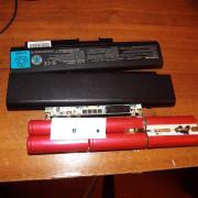
Realistically, you’ll only really need a cross-over cable if you’re dealing with very old hardware (like a hub
What’s the Difference Between Routers, Hubs, and Switches?
What’s the Difference Between Routers, Hubs, and Switches?
Are you confused about the differences between a hub, a switch, and a router? Don’t worry. The answer is actually quite simple. In this article, we break it down for you.
Read More
), or if you’re wanting to quickly connect two computers in a network-less environment.
Even then, nearly all modern hardware will automatically detect what you’re trying to do and configure the Ethernet port appropriately, without the need for a cross-over cable.
Making The Cable
Start by threading some shields onto the cable, it will be easier to do it now rather than later.
Strip about 1.5cm of cable shielding from both ends. Your crimping tool should have a round area specifically for this task.
Untangle the wires (there should be 4 “twisted pairs”). Arrange them in the order shown on the sheet from top to bottom; one end should be in arrangement A, the other B.
When you’ve got the order correct, bunch them together in a line. If you have some that stick up beyond the others, snip them back to a uniform level.
The hardest part is placing these into the RJ45 plug without messing up the order. Hold the plug with the clip side facing away from you; the gold pins should be facing towards you, as shown below.
Push the cable right in — the notch at the end of the plug should just be over the cable shielding. If it isn’t, you stripped too much shielding off. Snip the cables back a little more.
When the wires are sitting tightly in the plug, insert it into the crimping tool and push down. In theory the crimper is shaped to the exact right size, but in practice I find pushing too hard can crack the brittle plastic plug.
Repeat for the other end, using diagram B instead.
If you don’t have a cable tester, the easiest way to test is just to plug it in. Try connecting two computers directly together. The status LEDs vary by device, but typically one will show activity while the other indicates speed.
Распиновка выводов перекрестного кабеля
Витая пара
Перекрёстный кабель соединяющий два MDI порта
На практике не имеет значения какому стандарту, T568A или T568B, соответствует кабель, до тех пор пока оба его конца обжаты по одному и тому же стандарту. Обычно, коммерчески доступные «предварительно обжатые» кабели могут быть обжаты любым способом, в зависимости от производителя. Это значит, что кабели одного производителя обжаты одним способом, а другого другим, тем не менее оба будут верно работать. В любом случае, у прямого кабеля оба конца будут разведены либо по T568A, либо по T568B, соответственно в колонке Соединение 1 и колонке Соединение 2.
Определенным устройствам, включая те, в которых телефон и/или питание передаются вперемешку с данными в одном кабеле, может понадобиться, чтобы пары 1 и 4 (4,5,7 и 8 контакты) остались не перекрещенными.
| Контакт | Соединение 1: T568A | Соединение 2: T568B | Контакты на коннекторе | ||||
|---|---|---|---|---|---|---|---|
| сигнал | пара | цвет | сигнал | пара | цвет | ||
| 1 | BI_DA+ | 3 | белый/зеленая полоса | BI_DB+ | 2 | белый/оранжевая полоса | |
| 2 | BI_DA- | 3 | зеленый | BI_DB- | 2 | оранжевый | |
| 3 | BI_DB+ | 2 | белый/оранжевая полоса | BI_DA+ | 3 | белый/зеленая полоса | |
| 4 | 1 | синий | 1 | синий | |||
| 5 | 1 | белый/синяя полоса | 1 | белый/синяя полоса | |||
| 6 | BI_DB- | 2 | оранжевый | BI_DA- | 3 | зеленый | |
| 7 | 4 | белый/коричневая полоса | 4 | белый/коричневая полоса | |||
| 8 | 4 | коричневый | 4 | коричневый |